Device and method for 3D height-finding avian radar

a technology of avian radar and height-finding device, which is applied in the direction of measurement device, radio wave reradiation/reflection, and using reradiation, etc., can solve the problems of not accurately estimating the height (within the beam extent) of the system, and the significant hazard of birds to aviation safety

Active Publication Date: 2008-10-30
ACCIPITER RADAR TECH
View PDF24 Cites 57 Cited by
  • Summary
  • Abstract
  • Description
  • Claims
  • Application Information

AI Technical Summary

Benefits of technology

[0018]It is an object of the present invention to provide improved state-of-the-art a

Problems solved by technology

Birds are a significant hazard to aviation safety.
Applications that require bird monitoring are the bird aircraft strike hazard (BASH) problem and the natural resource management (NRM) problem.
Billions of dollars in damage to aircraft and significant loss of life have been recorded due to birds flying into aircraft, particularly during take-off and landing in the vicinity of airports.
These systems do not estimate height (within the beam extent) in any real sense.
However, as-is, these radars deliver mediocre performance for bird targets because of their primitive signal processing.
Such systems cannot provide useful height estimates of tracked targets when the radar is spinning horizontally in its usual orientation.
This means that if both a plane and a bird are being tracked by the radar at a distance of 1 km away, the radar cannot tell whether the two targets are 1,000 feet apart (i.e. one is on the ground and the other is at the upper edge of the vertical beam, 1,000 feet off the ground) or whether they are at the same altitude where a collision could occur.
While some radar config

Method used


Image

  • Device and method for 3D height-finding avian radar
  • Device and method for 3D height-finding avian radar
  • Device and method for 3D height-finding avian radar

Examples


Embodiment Construction

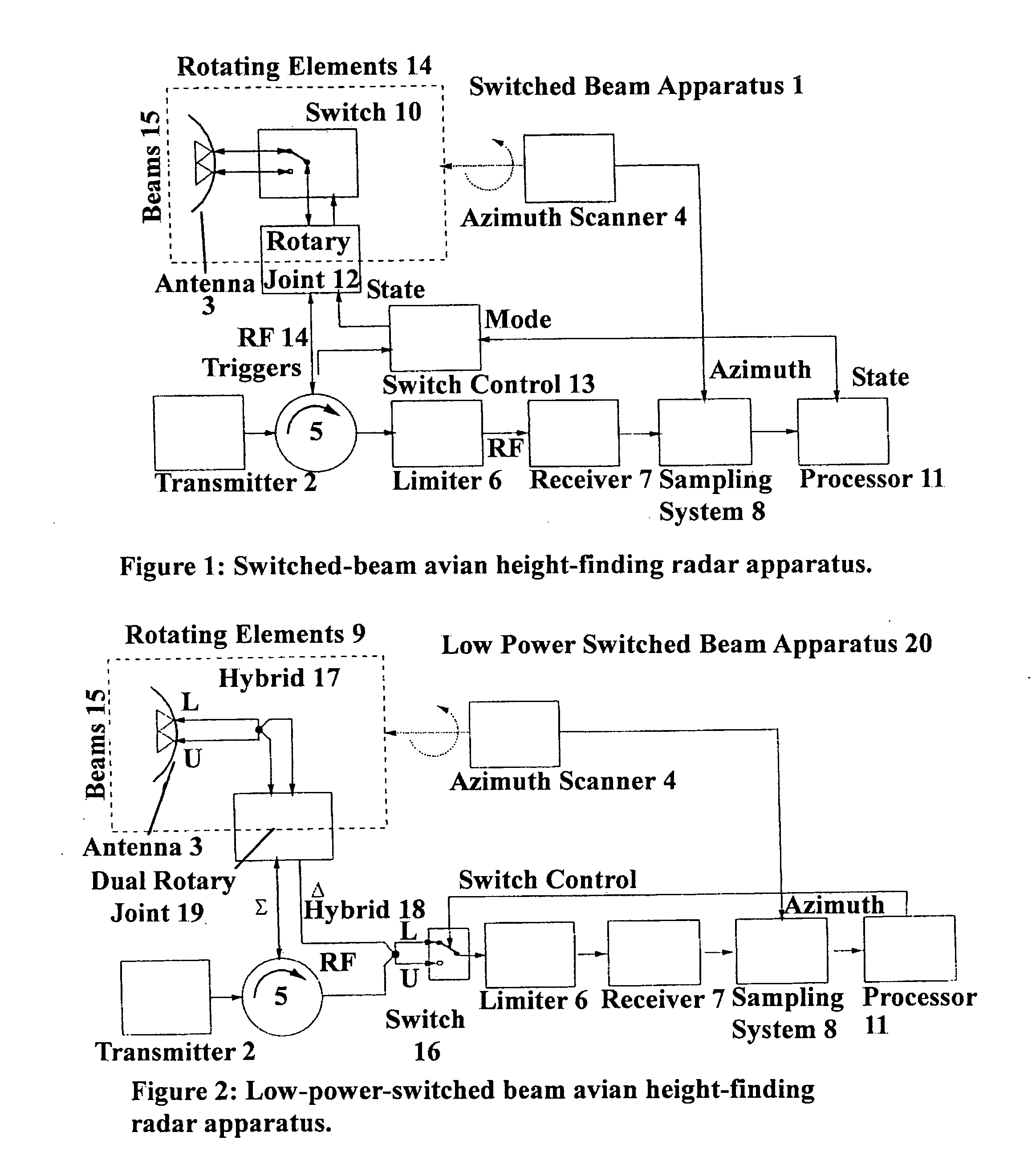
[0059]A block diagram of a switched-beam avian height-finding radar apparatus 1 in accordance with the present invention is shown in FIG. 1. Characteristics of each block are as follows. The avian height-finding radar apparatus 1 includes a radar transmitter 2 that is typically noncoherent and transmits pulses of constant width at a constant pulse repetition frequency (PRF) at X-band or S-Band (or other bands). Radar apparatus 1 typically has either a continuously rotating or sector-scanning antenna 3. Antenna 3 is typically mounted near ground level within (or near) the area to be monitored.

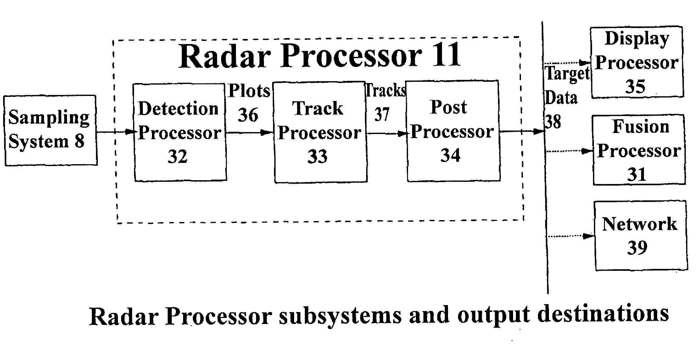
[0060]The azimuth scanner 4 rotates the antenna 3 continuously in azimuth while the antenna 3 is transmitting and receiving. The circulator 5, limiter 6 and receiver 7 are conventional radar components such as those found in marine radar transceivers. The sampling system, 8 digitizes the radar return video signal.

[0061]The switched-beam antenna 3 has (at least) 2 selectable radar beams 15 pointe...


PUM


Abstract

A height-finding 3D avian radar comprises an azimuthally scanning radar system with means of varying the elevation pointing angle of the antenna. The elevation angle can be varied by employing either an antenna with multiple beams, or an elevation scanner, or two radars pointed at different elevations. Heights of birds are determined by analyzing the received echo returns from detected bird targets illuminated with the different elevation pointing angles.

Description

FIELD OF THE INVENTION[0001]This invention relates to ground-based radar systems and methods. The invention relates more additionally and more specifically to radar target detection, tracking and estimation of target height. The invention is particularly useful in radar surveillance of birds and other airborne targets.BACKGROUND OF THE INVENTION[0002]Avian radars are used to track birds in flight in the vicinity of airfields, wind farms, communications towers, and along migration routes. Birds are a significant hazard to aviation safety. Applications that require bird monitoring are the bird aircraft strike hazard (BASH) problem and the natural resource management (NRM) problem. Billions of dollars in damage to aircraft and significant loss of life have been recorded due to birds flying into aircraft, particularly during take-off and landing in the vicinity of airports.[0003]The danger associated with birds depends on their altitude (among other factors). Users of bird detection and...

Claims


Application Information

Patent Timeline
IPC IPC(8): G01S13/08
CPCG01S7/003G01S13/424G01S13/426G01S13/726
Inventor WEBER, PETER T.NOHARA, TIMOTHY J.
Owner ACCIPITER RADAR TECH
Why Eureka
Try Eureka