Device and method to realize a light processor

a technology of light processors and devices, applied in the direction of mirrors, instruments, mountings, etc., can solve the problems of failure to address other problems, damage to the hinge itself, and the slow lifting of the landing tips from the pads,

Inactive Publication Date: 2008-10-30
AGENCY FOR SCI TECH & RES
View PDF5 Cites 164 Cited by
  • Summary
  • Abstract
  • Description
  • Claims
  • Application Information

AI Technical Summary

Benefits of technology

[0010]The present invention provides a fluid or gel-based light processing system that overcomes the above problems. In particular, the present invention provides methods and systems for digital light processing for TVs, projectors, and other displays that eliminates the use of mechanical micro-mirrors.

Problems solved by technology

However, one problem with conventional DLP devices is the problem of stuck mirrors, where the landing tips are slow to lift from the pads or become permanently stuck to the pads.
This ‘sticking problem’ is an important consideration for reliable performance, since it is the most frequent cause of device failure.
Sources of the sticking problem may include moisture in the package, scrubbing of landing tips onto the metal landing pads, and outgassing of the epoxy sealants used in the manufacturing process for mounting the devices in their packages.
However, the above solutions fail to address other problems.
For example, the hinge itself may become damaged or defective.
Moreover, some of the above solutions suffer from long-term degradation of the passivant, which could drive the technology to require hermetic packages and complex process steps.
Other problems that remain unaddressed include heating of the chip and difficult thermal management of the micro-mirrors, which must be cooled.
An additional problem is the “pixel effect” or background noise characterized by stray points of light appearing on the display screen.

Method used


Image

  • Device and method to realize a light processor
  • Device and method to realize a light processor
  • Device and method to realize a light processor

Examples


Embodiment Construction

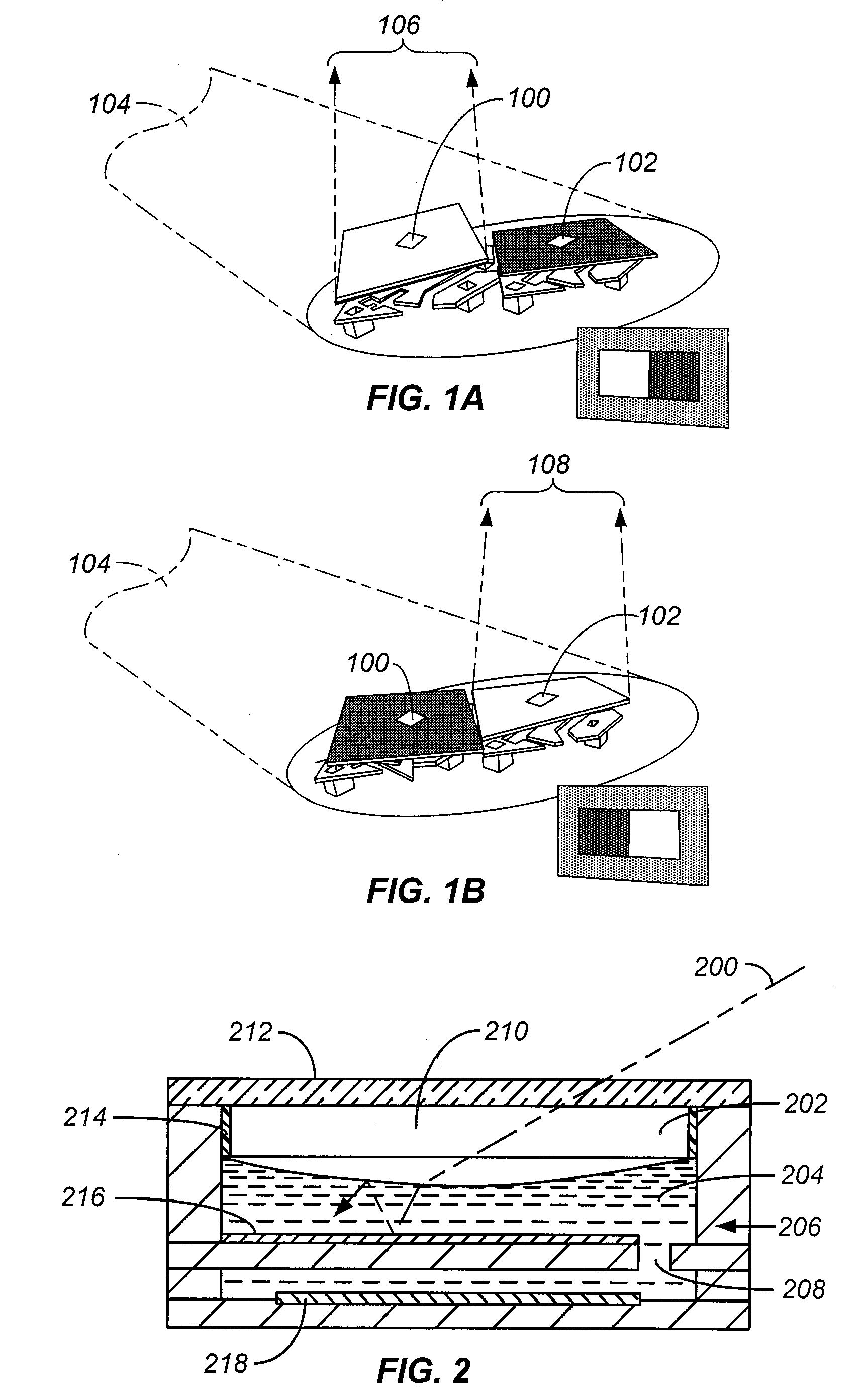
[0043]A source of light directed at a conventional DLP array is typically reflected in one of two directions for each micro-mirror, or pixel. In one direction, the pixel is “off” so that incident light directed upon the mirror will be deflected to a light absorber. In the other direction, the pixel is in the “on” position, so that light incident to that pixel will be reflected to a projector lens. The projector lens then focuses and magnifies the modulated light from the pixel onto a display screen, or to a photosensitive element of a printer. If each pixel of the array is in the “on” position for the case of a display, the displayed image will be an array of bright spots or areas.

[0044]FIGS. 1A and 1B show two pixels of a conventional DLP chip in the “on” and “off” modes. FIG. 1A shows two DLP cells with the left pixel 100 turned on and the right pixel 102 turned off. Incident light 104 hits both pixels, but only left pixel 100 reflects back light 106 to a projector lens, while rig...


PUM


Abstract

A device for light processing includes a first housing having a reflective bottom surface and walls defining a first cavity. A first fluid or gel has a meniscus disposed within the first cavity. A control means is coupled with the first fluid or gel for adjusting the curvature of the meniscus. The bottom surface is configured to reflect an incident light beam through the first fluid or gel and toward the meniscus.

Description

CROSS-REFERENCES TO RELATED APPLICATIONS[0001]This application claims the priority to U.S. Provisional Patent Application No. 60 / 857,605, filed Nov. 7, 2006, which is hereby incorporated by reference in its entirety for all purposes.BACKGROUND OF THE INVENTION[0002]The present invention relates to light processors and more specifically to digital light processors that eliminate the need for micro-mirror devices.[0003]Space light modulators are transducers that modulate incident light in a spatial pattern corresponding to an electrical or optical input. The incident light may be modulated in its phase, intensity, polarization, or direction, and the light modulation may be achieved by using elements made of a variety of materials exhibiting various electro-optic or magneto-optic effects and by materials that modulate light by surface deformation.[0004]Digital light processors (DLP) are light modulators suitable for various applications such as displays, projectors, televisions, monito...

Claims


Application Information

Patent Timeline
Patent Type & Authority Applications(United States)
IPC IPC(8): G02B26/08
CPCG02B26/004
Inventor DHARMATILLEKE, SAMAN
Owner AGENCY FOR SCI TECH & RES
Why Eureka
Try Eureka