

Optical apparatus, multilayer-film reflective mirror, exposure apparatus, and device
a reflective mirror and optical technology, applied in the direction of lighting and heating apparatus, photomechanical apparatus, instruments, etc., can solve the problems of deterioration in the performance of the exposure apparatus, occurrence of defective exposure, and difficulty in reducing undesirable light in a wide wavelength range of a single multi-layer-film reflective mirror. achieve the effect of reducing undesirable light or eliminating undesirable light, suppressing deterioration in optical performance, and achieving desired performan
- Summary
- Abstract
- Description
- Claims
- Application Information
AI Technical Summary
Benefits of technology
Problems solved by technology
Method used
Image

Examples
first embodiment
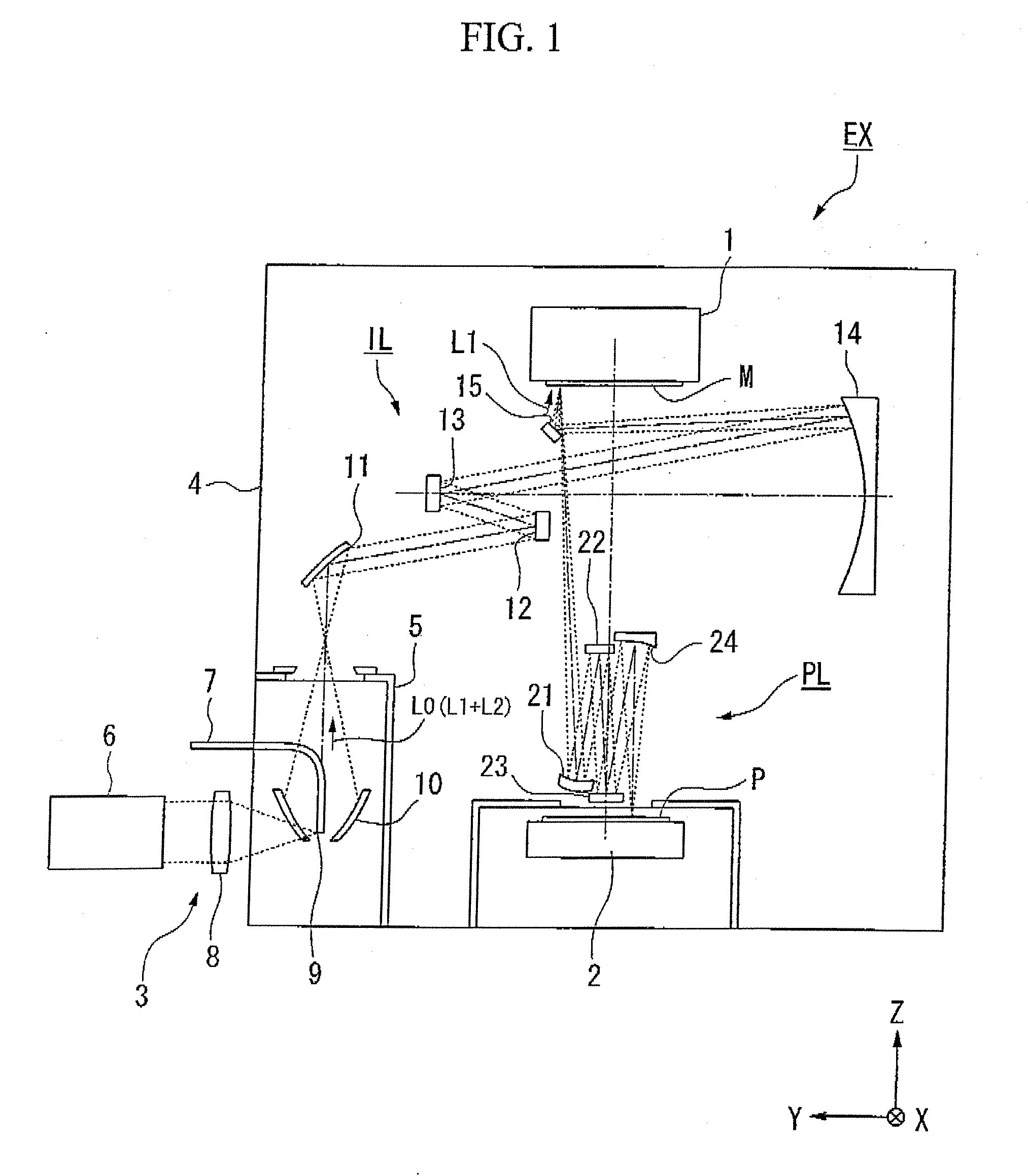
[0045]A first embodiment will be described. FIG. 1 is a schematic block diagram showing one example of an exposure apparatus EX according to a first embodiment. In FIG. 1, the exposure apparatus EX includes: a mask stage 1 capable of moving while holding a mask M on which a pattern is formed; a substrate stage 2 capable of moving while holding a substrate P for forming devices; a light source apparatus 3 for generating exposure light; an illumination optical system IL for illuminating a mask M held on the mask stage 1 with exposure light EL emitted from the light source apparatus 3; a projection optical system PL for projecting an image of a pattern on the mask M illuminated by the exposure light onto the substrate P.
[0046]The exposure apparatus EX in the present embodiment is an EUV exposure apparatus that exposes the substrate P with extreme ultraviolet light. Extreme ultraviolet light is an electromagnetic wave in an extreme ultraviolet region (soft X-ray region) at a wavelength ...
second embodiment
[0097]Next is a description of a second embodiment. In the following description, components the same as or similar to those of the aforementioned embodiment are denoted by the same reference symbols, and descriptions thereof are simplified or omitted.
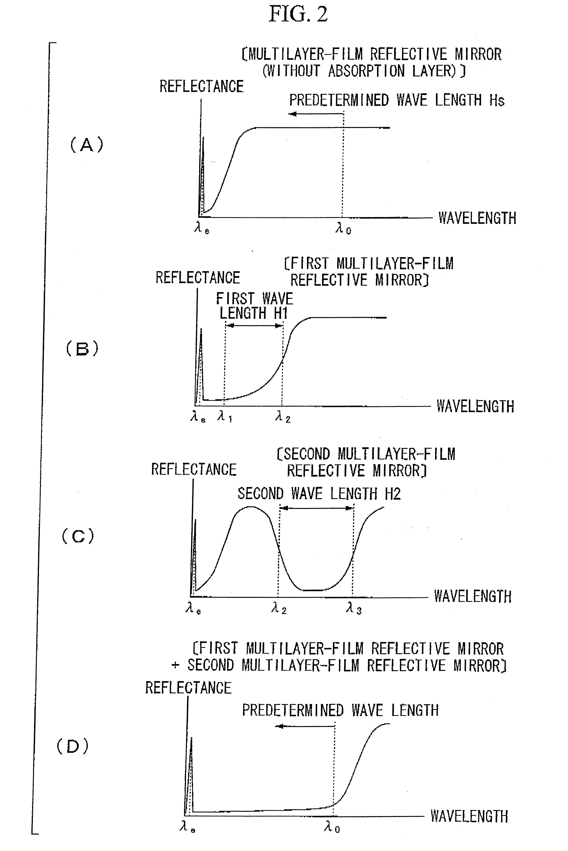
[0098]In the present embodiment, the case is described where of the condensing mirror 10 and the plurality of multilayer-film reflective mirrors 11 to 15 of the illumination optical system IL, at least one multilayer-film reflective mirror is a first multilayer-film reflective mirror 41B shown in FIG. 8, and at least one multilayer-film reflective mirror is a second multilayer-film reflective mirror 42B shown in FIG. 9.
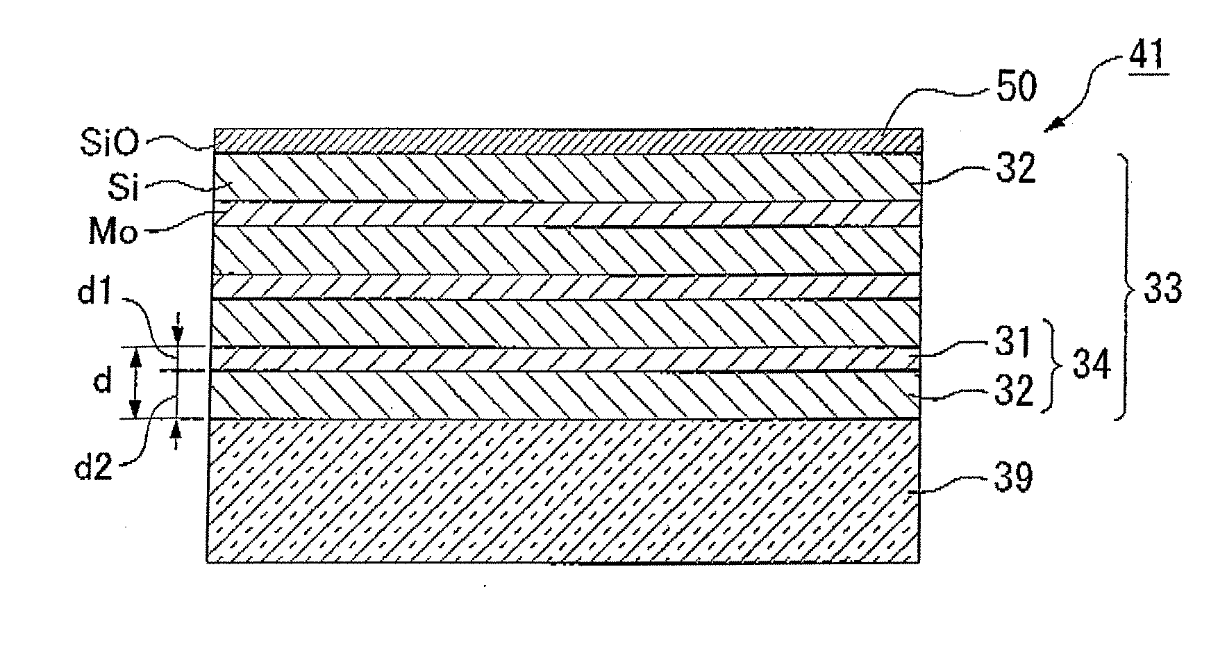
[0099]First, the first multilayer-film reflective mirror 41B will be described. In FIG. 8, the first multilayer-film reflective mirror 41B includes: a base 39; a multilayer film 33 that includes first layers 31 and second layers 32 alternately laminated on the base 39 at a predetermined periodic length “d” and is capable...
third embodiment
[0111]Next is a description of a third embodiment. In the following description, components the same as or similar to those of the aforementioned embodiments are denoted by the same reference symbols, and descriptions thereof are simplified or omitted.
[0112]In the present embodiment, the case is described where of the condensing mirror 10 and the plurality of multilayer-film reflective mirrors 11 to 15 of the illumination optical system IL, at least one multilayer-film reflective mirror is a first multilayer-film reflective mirror 41 shown in FIG. 3 above, and at least one multilayer-film reflective mirror is a second multilayer-film reflective mirror 42C shown in FIG. 13.
[0113]The first multilayer-film reflective mirror is the first multilayer-film reflective mirror 41 which was described with reference to FIG. 3 above, and hence the description thereof is omitted. Furthermore, the reflecting wavelength characteristic of the first multilayer-film reflective mirror 41 was described ...
PUM
 Abstract
Description
Claims
Application Information