Camera module

a technology of camera module and supporting part, which is applied in the direction of mounting, focusing aids, instruments, etc., can solve the problems of difficult to obtain a leaf spring having a predetermined load characteristic, inability to ensure a stable driving force of the holder, and inability to adjust the resiliency of the supporting part. , to achieve the effect of reducing the number of necessary components and easy adjustment of the resiliency of the supporting par

Active Publication Date: 2008-10-30
MITSUMI ELECTRIC CO LTD
View PDF8 Cites 10 Cited by
  • Summary
  • Abstract
  • Description
  • Claims
  • Application Information

AI Technical Summary

Benefits of technology

[0025]With this structure, by appropriately selecting an extending length of the extending part, it is possible to easily adjust the resiliency of the supporting part.
[0026]Furthermore, in the camera module of the present invention, it is also preferred that the bridge portion ...

Problems solved by technology

Due to the unevenness of the thickness of the metal plate, there is a problem in that a load characteristic when it is used as the upper leaf spring 104 and the lower leaf spring 110 is not stable.
Further, a load characteristic of the leaf spring is affected by a heat treatment applied during the manufacturing process of the upper...

Method used


Image

  • Camera module
  • Camera module
  • Camera module

Examples


Embodiment Construction

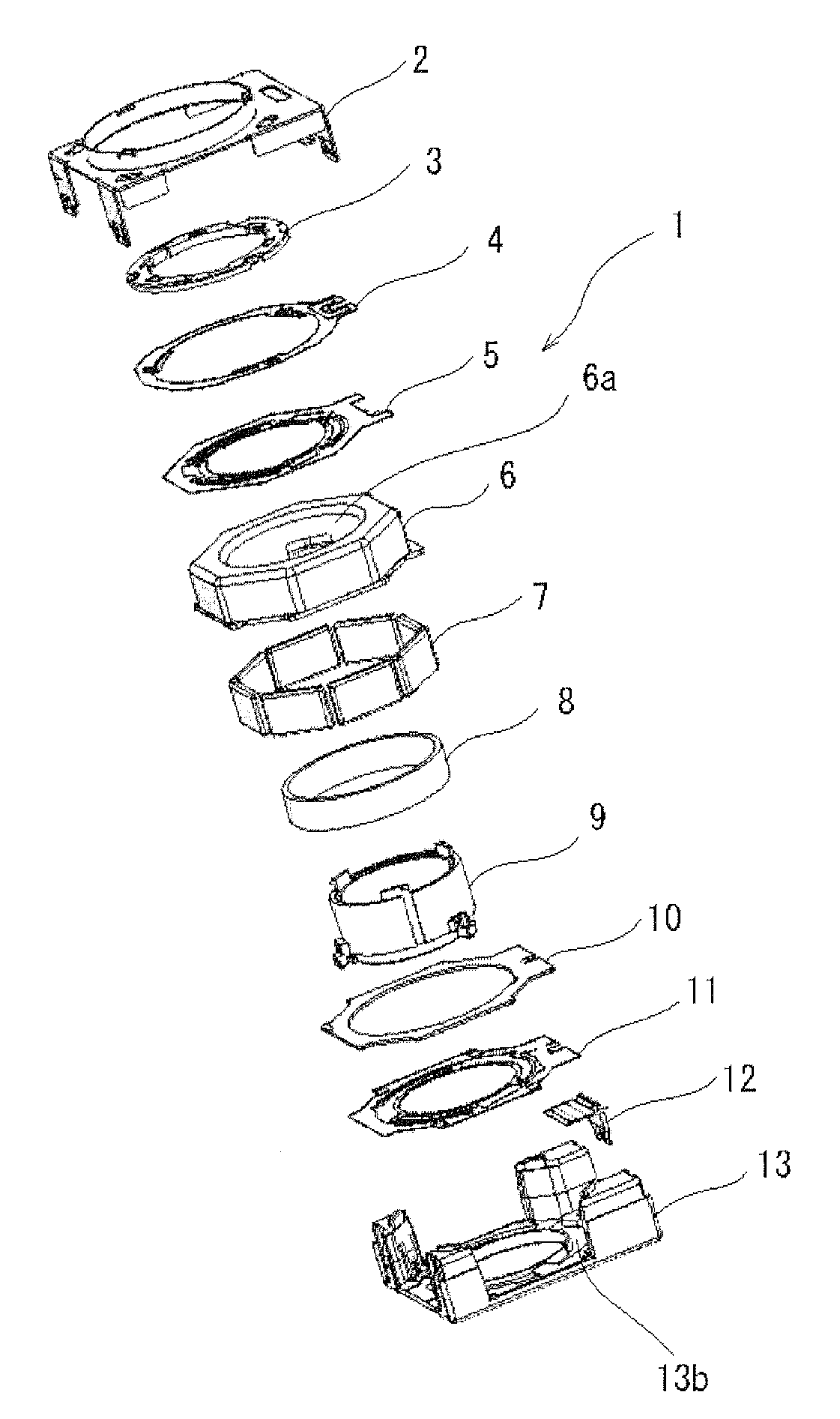
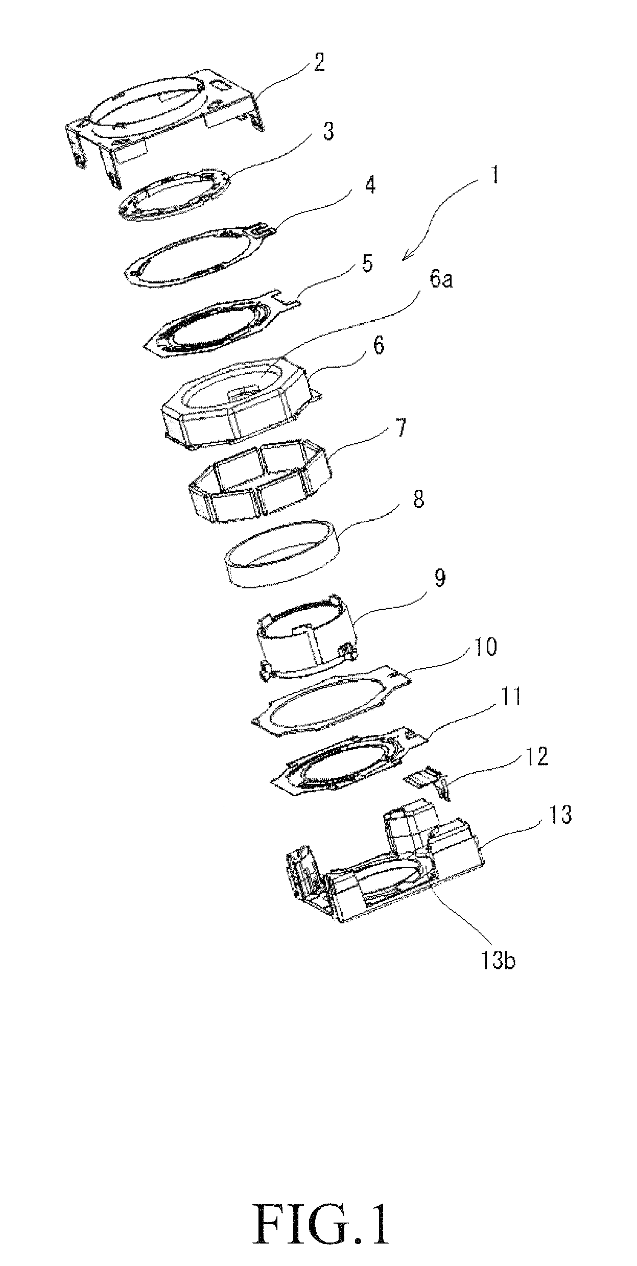
[0043]A camera module according to an embodiment of the present invention will be described below with reference to the accompanying drawings.

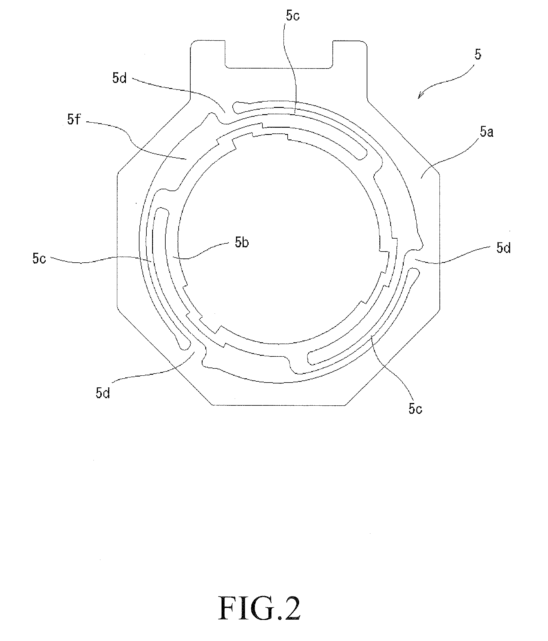
[0044]The camera module according to the embodiment includes a lens unit (not shown in the drawings) which constitutes an optical system of the camera module; a holder 9 which houses the lens unit and is displaceable along an optical axis direction of the lens unit; a coil 8 provided on the holder 9; a yoke 6 and a plurality of magnets 7 provided on the yoke 6 for providing a magnetic field to the coil 8; an upper leaf spring 5 for supporting the holder 9, the leaf spring 5 including an outer annular portion 5a, an inner annular portion 5b provided inside the outer annular portion 5a so as to be displaceable with respect to the outer annular portion 5a and attached to the holder 8, and a plurality of bridge portions 5c coupled between the outer annular portion 5a and the inner annular portion 5b; and an imaging element (not shown in the drawin...


PUM


Abstract

A camera module includes upper and lower leaf springs having a stable load characteristic and a holder displaceably held by the leaf springs so that the holder can be stably displaced within a magnetic circuit. The upper spring 5 has an outer annular portion 5a, an inner annular portion 5b provided inside the outer annular portion 5a so as to be displaceable with respect to the outer annular portion 5a and attached to the holder 9, and a plurality of bridge portions 5c coupled between the outer annular portion 5a and the inner annular portion 5b. The camera module further includes a bridge portion supporting member 4 for supporting a part of at least one of the plurality of bridge portions so that a load characteristic of the leaf spring can be changed. By rotating the bridge portion supporting member 4 in a clockwise direction, an overlapping part between the extending part 4c and the bridge portion 5c is increased according to the amount of the rotation so that a spring constant of the upper leaf spring 5 is apparently increased.

Description

BACKGROUND OF THE INVENTION[0001]1. Field of the Invention[0002]This invention relates to a camera module, and more specifically to a camera module that can be used in small-sized electronic apparatuses such as digital cameras, camera-equipped cellular phones and the like.[0003]2. Description of the Prior Art[0004]A camera module having a function of displacing a lens unit in a direction of an optical axis of the lens unit is used in relatively small-sized digital cameras and camera-equipped cellular phones and the like. This function is used for providing an autofocus function and / or zoom function and the like, and is achieved by an interaction between a magnetic field generated by an electrical current flowing in a coil and a magnetic field generated by a yoke and magnets provided on the yoke.[0005]Such a camera module includes a barrel which holds the lens unit, a holder which houses the barrel therein, and a pair of leaf springs for supporting the holder so that the holder is di...

Claims


Application Information

Patent Timeline
IPC IPC(8): G02B7/04
CPCG02B7/08G02B7/102G03B13/34
Inventor ISHIZAWA, TAKASHIOSAKA, TOMOHIKO
Owner MITSUMI ELECTRIC CO LTD
Why Eureka
Try Eureka