
Power supply apparatus having multiple outputs

Active Publication Date: 2008-10-30
HEWLETT PACKARD DEV CO LP
View PDF6 Cites 12 Cited by
  • Summary
  • Abstract
  • Description
  • Claims
  • Application Information

AI Technical Summary

Benefits of technology

[0017]Aspects of the present invention provide a power supply apparatus having multiple outputs capable of having a plurality of output circuits in the secondary side of a transformer, individually controlling an output voltage of each output circuit, increasing efficiency by reducing power losses, and having a simple configuration.
[0031]The current source type switching circuit may further include a snubber circuit to prevent leakage inductance of the transformer.

Problems solved by technology

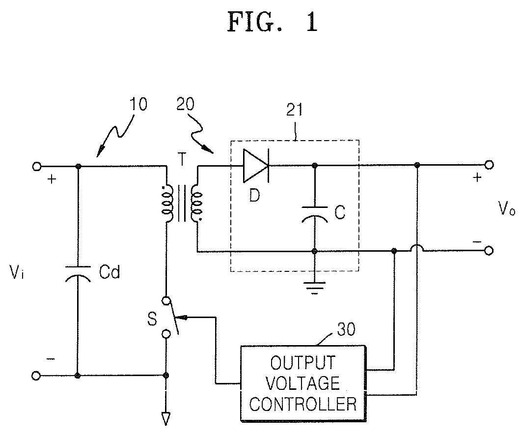
However, the conventional current source type power supply apparatuses having multiple outputs use multiple transformers, and include multiple regulator chips that may cause heavy losses in order to control a voltage output from each secondary circuit, or have complex structures in which an output voltage feedback circuit of each secondary circuit is connected to the primary circuit.
As a result, the aforementioned advantage of the current source type power supply apparatus cannot be effectively applied.

Method used


Image

  • Power supply apparatus having multiple outputs
  • Power supply apparatus having multiple outputs
  • Power supply apparatus having multiple outputs

Examples


Embodiment Construction

[0045]Reference will now be made in detail to the present embodiments of the present invention, examples of which are illustrated in the accompanying drawings, wherein like reference numerals refer to the like elements throughout. The embodiments are described below in order to explain the present invention by referring to the figures.

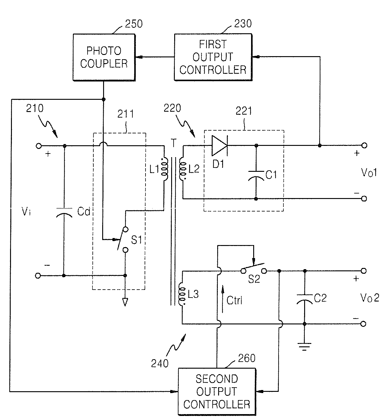
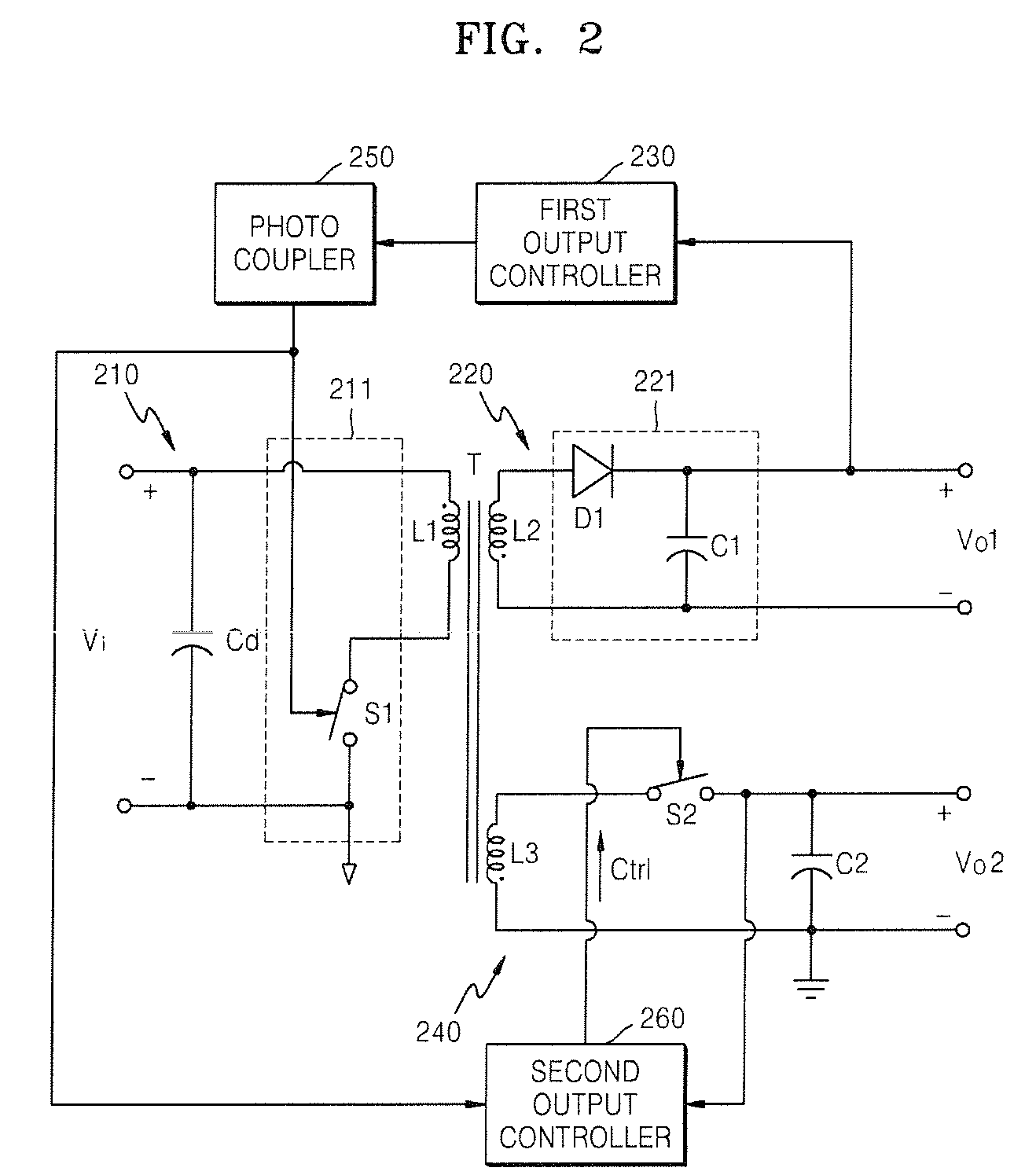
[0046]FIG. 2 is a circuit diagram explaining a power supply apparatus having multiple outputs according to an example embodiment of the present invention. According to the example embodiment of the present invention, the power supply apparatus includes two outputs. However, it is understood that according to aspects of the present invention, the power supply apparatus may be constructed to output N number of output voltages, where N is a natural number. When the number of outputs is N, a transformer includes N number of secondary coils, such that each of the N number of secondary coils may be connected to each secondary output circuit.

[0047]As illustra...


PUM


Abstract

A power supply apparatus having multiple outputs, a transformer, a first output circuit generating a first output voltage with respect to power transferred to a secondary side of the transformer, and a first output controller generating a first control signal to control a power supply provided to a primary side of the transformer, the apparatus including: a second output circuit to generate a second output voltage with respect to the power transferred to the secondary side of the transformer; and a second output controller to control an output of the second output voltage, wherein the second output circuit includes a second switch performing a switching operation on current flows of the second output circuit, and the second output controller controls the switching operation of the second switch by turning off the second switch or feeding the second output voltage back to the second switch according to the first control signal.

Description

CROSS-REFERENCE TO RELATED APPLICATION[0001]This application claims all benefits accruing under 35 U.S.C. §119 from Korean Patent Application No. 2007-42191, filed on Apr. 30, 2007 in the Korean Intellectual Property Office, the disclosure of which is incorporated herein by reference.BACKGROUND OF THE INVENTION[0002]1. Field of the Invention[0003]Aspects of the present invention relate to a power supply apparatus having multiple outputs, and more particularly, to a power supply apparatus having multiple outputs capable of individually controlling multiple output voltages using a simple structure.[0004]2. Description of the Related Art[0005]In general, apparatuses such as a computer, an image forming apparatus (such as a printer or a copier), a monitor, or a communication terminal, require an efficient power supply system that has a simple structure and a small size to provide a stable power supply. A current source type power supply apparatus has been widely used as an efficient pow...

Claims


Application Information

Patent Timeline
IPC IPC(8): H02M3/335
CPCH02M3/33507H02M3/33561H02M3/28
Inventor KIM, JIN-HAKWON, JOONG-GI
Owner HEWLETT PACKARD DEV CO LP
Learn More