
Method and circuit assembly for sensorless load detection in stepper motors

Pending Publication Date: 2022-04-21
MAXIM INTEGRATED PROD INC
View PDF1 Cites 0 Cited by
  • Summary
  • Abstract
  • Description
  • Claims
  • Application Information

AI Technical Summary

Benefits of technology

The invention solutions have the advantage that they require very little chip surface area, which means that there is no need for expensive analog-digital converters or additional current measuring resistors. This results in lower costs and reduced power loss.

Problems solved by technology

No additional current measuring resistors are required, which would not only cause higher costs but also an increase in power loss.

Method used


Image

  • Method and circuit assembly for sensorless load detection in stepper motors
  • Method and circuit assembly for sensorless load detection in stepper motors
  • Method and circuit assembly for sensorless load detection in stepper motors

Examples


Embodiment Construction

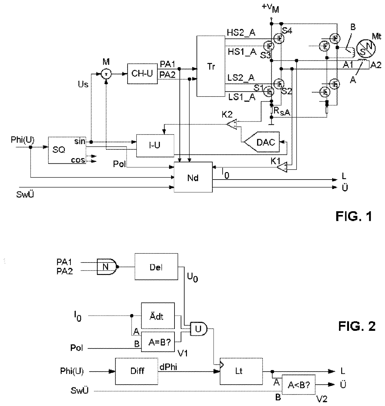
[0027]The invention is based on a method and a circuit assembly for controlling a stepper motor in a voltage-based (that is, voltage-controlled or voltage-regulated) operating mode according to the disclosure in WO 2015 / 192831. In the following description, therefore, substantially only the developments according to the invention of said known method or said known circuit assembly are explained, while reference is made to said document with regard to the method steps and circuit components that have been adopted unchanged.

[0028]FIG. 1 shows a block diagram of an embodiment of a circuit assembly for carrying out the method according to the invention for a first coil A of a stepper motor Mt. The components shown are also to be provided in the same way for the second coil B (and, if applicable, each additional coil) of the stepper motor Mt to be controlled.

[0029]The circuit assembly comprises a bridge circuit formed from a first to fourth semiconductor switch S1, S2, S3, S4, the bridge...


PUM


Abstract

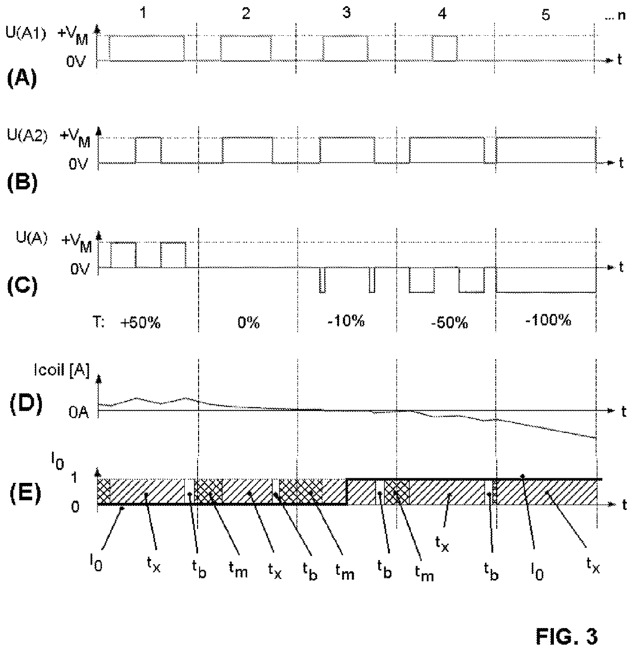
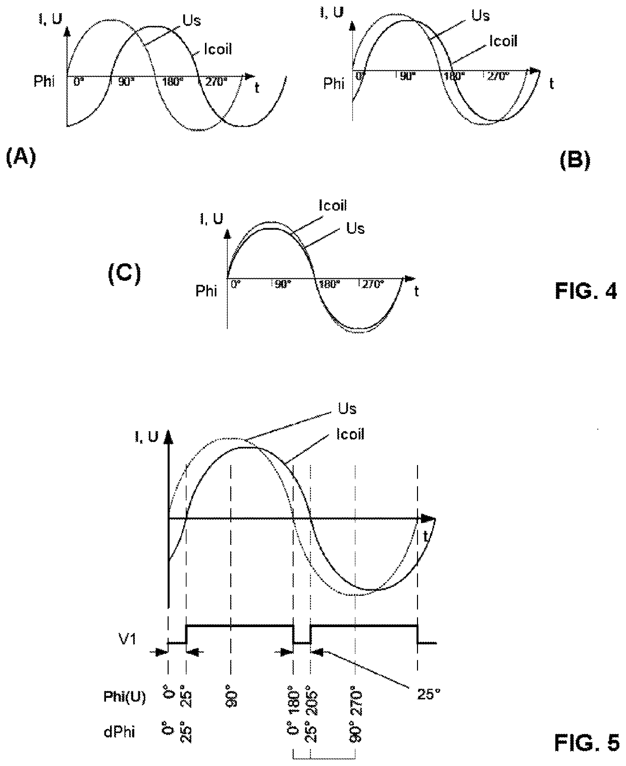
A method and a circuit assembly are described with which, in a stepper motor, a mechanical load applied to the motor shaft of which can be detected without a sensor in a voltage-based operating mode in which a nominal coil current is generated by applying a predetermined coil voltage (Us) to the coil. The coil is connected in a bridge branch of a bridge circuit formed from a first to fourth semiconductor switch (S1, . . . S4), wherein the predetermined coil voltage (Us) is applied to the coil with a variable duty cycle (T) by switching the semiconductor switch in the form of at least one PWM voltage (U(A1), U(A2)). The motor load is detected in the form of a load indicator signal (L) which represents a phase shift between a zero crossing of the predefined coil voltage (Us) and the next zero crossing of the coil current (Icoil) generated thereby, wherein a zero crossing of the coil current (Icoil) is defined when, in those time intervals (tm) in which the PWM voltage (U(A1), U(A2)) applied to the coil is zero, a polarity change occurs in a voltage dropping across the internal resistances of the semiconductor switches due to the coil current.

Description

CROSS REFERENCE TO RELATED PATENT APPLICATIONS[0001]The present application claims priority benefit to the PCT Application No. PCT / DE2019 / 100933, filed on Oct. 29, 2019, entitled “ METHOD AND CIRCUIT ASSEMBLY FOR SENSORLESS LOAD DETECTION IN STEPPER MOTORS,” listing as inventor Bernhard Dwersteg, which claims priority benefit to German Patent Application, Serial Number 102018126954.4 entitled “METHOD AND CIRCUIT ASSEMBLY FOR SENSORLESS LOAD DETECTION IN STEPPER MOTORS”, filed on Oct. 29, 2018 and listing as inventor Bernhard Dwersteg. Each reference mentioned in this patent document is incorporated by reference herein in its entirety and for all purposes.TECHNICAL FIELD[0002]The invention relates to a method and a circuit assembly with which, in a stepper motor, a mechanical load applied to the motor shaft thereof can be detected without sensors in a voltage-based (that is, voltage-controlled for voltage-regulated) operating mode. The invention can be used for 2-phase and for 3- or ...

Claims


Application Information

Patent Timeline
IPC IPC(8): H02P8/34
CPCH02P8/34
Inventor DWERSTEG, BERNHARD
Owner MAXIM INTEGRATED PROD INC
Learn More