Piezoelectric element driving circuit and fluid control apparatus
- Summary
- Abstract
- Description
- Claims
- Application Information
AI Technical Summary
Benefits of technology
Problems solved by technology
Method used
Image
Examples
second embodiment
[0079]A fluid control apparatus 200 according to a second embodiment of the present disclosure will be described with reference to the drawings.
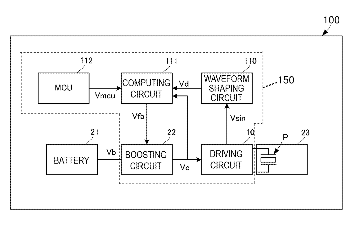
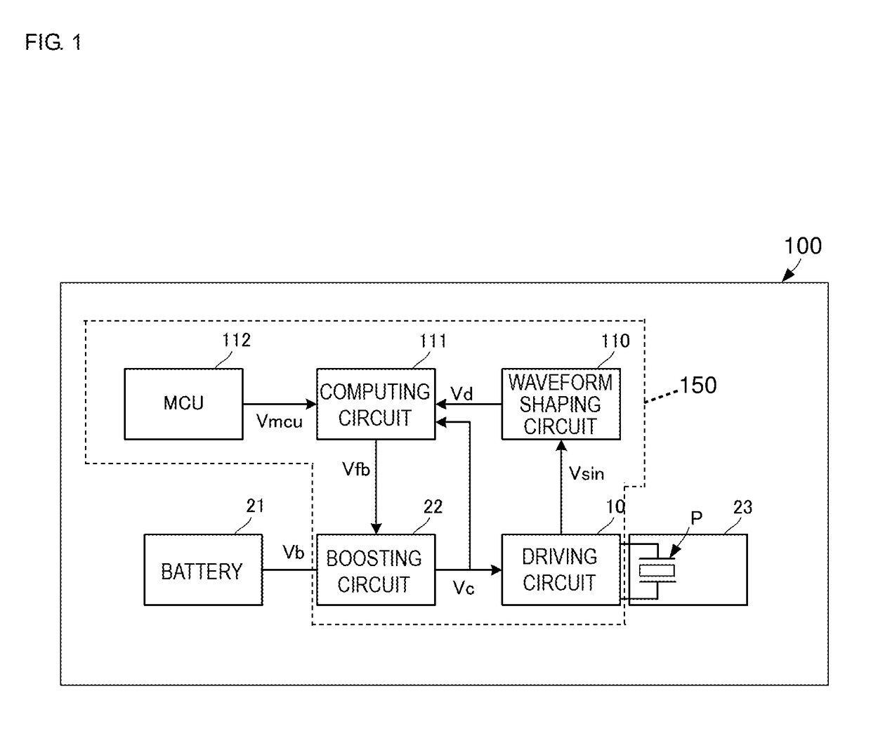
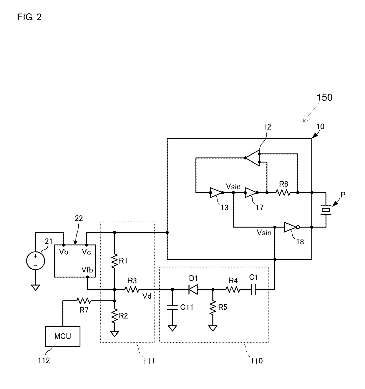
[0080]FIG. 9 is a block diagram illustrating a configuration of the fluid control apparatus 200 according to the second embodiment. FIG. 10 is a circuit diagram illustrating a configuration of a driving circuit 210 illustrated in FIG. 9. FIG. 11 illustrates voltage waveforms in a piezoelectric element driving circuit 250 illustrated in FIG. 9. The fluid control apparatus 200 is identical to the fluid control apparatus 100 except for the piezoelectric element driving circuit 250. The other components are the same and will not be described here.
[0081]The output terminal of the MCU 112 is connected to the input terminal of the inverter 18. The output terminal of the inverter 18 is connected to the second terminal of the piezoelectric element P. The MCU 112 generates a reference signal fc and outputs it to the inverter 18.
[0082]As illustrated in...
third embodiment
[0092]A fluid control apparatus 300 according to a third embodiment of the present disclosure will be described with reference to the drawings.
[0093]FIG. 12 is a block diagram illustrating a configuration of the fluid control apparatus 300 according to the third embodiment. The fluid control apparatus 300 is identical to the fluid control apparatus 100 except for a piezoelectric element driving circuit 350. The piezoelectric element driving circuit 350 differs from the piezoelectric element driving circuit 150 in that the computing circuit 111 is omitted and an MCU 312 is connected to the waveform shaping circuit 110 and the boosting circuit 22 instead. In the present embodiment, the waveform shaping circuit 110 and the MCU 312 form the control circuit of the present disclosure.
[0094]The MCU 312 refers to the voltage Vd input from the waveform shaping circuit 110, computes a voltage Vmcu at which the piezoelectric element P vibrates with a given amplitude, and then outputs the volta...
fourth embodiment
[0099]A fluid control apparatus 400 according to a fourth embodiment of the present disclosure will be described with reference to the drawings.
[0100]FIG. 13 is a block diagram illustrating a configuration of the fluid control apparatus 400 according to the fourth embodiment. The fluid control apparatus 400 is identical to the fluid control apparatus 100 except for a computing circuit 411 in a piezoelectric element driving circuit 450. The computing circuit 411 differs from the computing circuit 111 in that it further includes an FET M1. The other components of the fluid control apparatus 400 are the same as those of the fluid control apparatus 100, and the description of the same points will be omitted here.
[0101]The computing circuit 411 includes the FET M1 and the resistors R1, R2, and R3. The gate terminal of the FET M1 is connected to the waveform shaping circuit 110. The source terminal of the FET M1 is connected to one end of the resistor R3. The other end of the resistor R3 ...
PUM
 Abstract
Description
Claims
Application Information
 - R&D
- Intellectual Property
- Life Sciences
- Materials
- Tech Scout
- Unparalleled Data Quality
- Higher Quality Content
- 60% Fewer Hallucinations
Browse by: Latest US Patents, China's latest patents, Technical Efficacy Thesaurus, Application Domain, Technology Topic, Popular Technical Reports.
© 2025 PatSnap. All rights reserved.Legal|Privacy policy|Modern Slavery Act Transparency Statement|Sitemap|About US| Contact US: help@patsnap.com


