Fan motor control unit

Active Publication Date: 2014-12-18
SANYO DENKI CO LTD
View PDF4 Cites 5 Cited by
  • Summary
  • Abstract
  • Description
  • Claims
  • Application Information

AI Technical Summary

Benefits of technology

[0014]With the fan motor control unit thus configured, the energization timing from the power source to the coil is advanced with respect to the energization timing applied while the current detected by the current sensor is lower than the thresh

Problems solved by technology

Thus, the circuit suffers greater power loss, with the increase of the load imposed on the fan motor.
In

Method used


Image

  • Fan motor control unit
  • Fan motor control unit
  • Fan motor control unit

Examples


Example

[0032]Hereafter, an embodiment of a fan motor control unit according to the present invention will be described.

Configuration of Fan Motor Control Unit

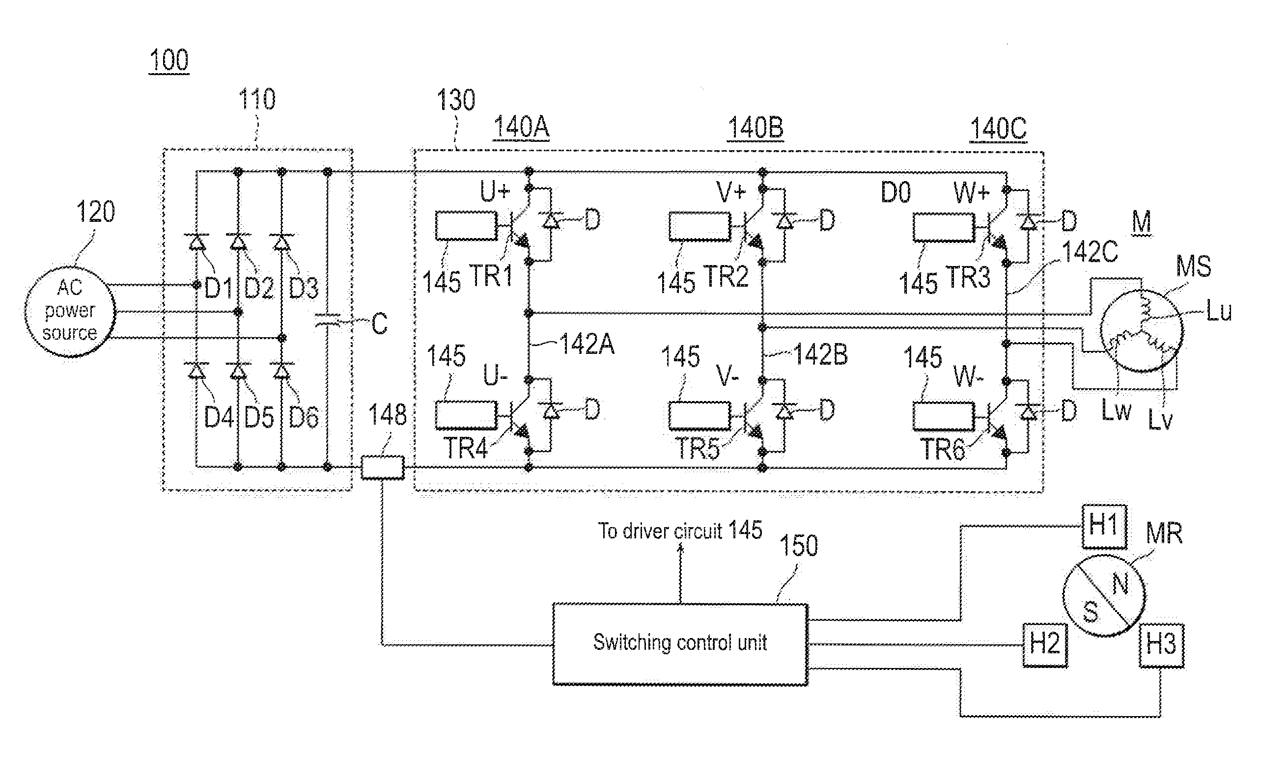
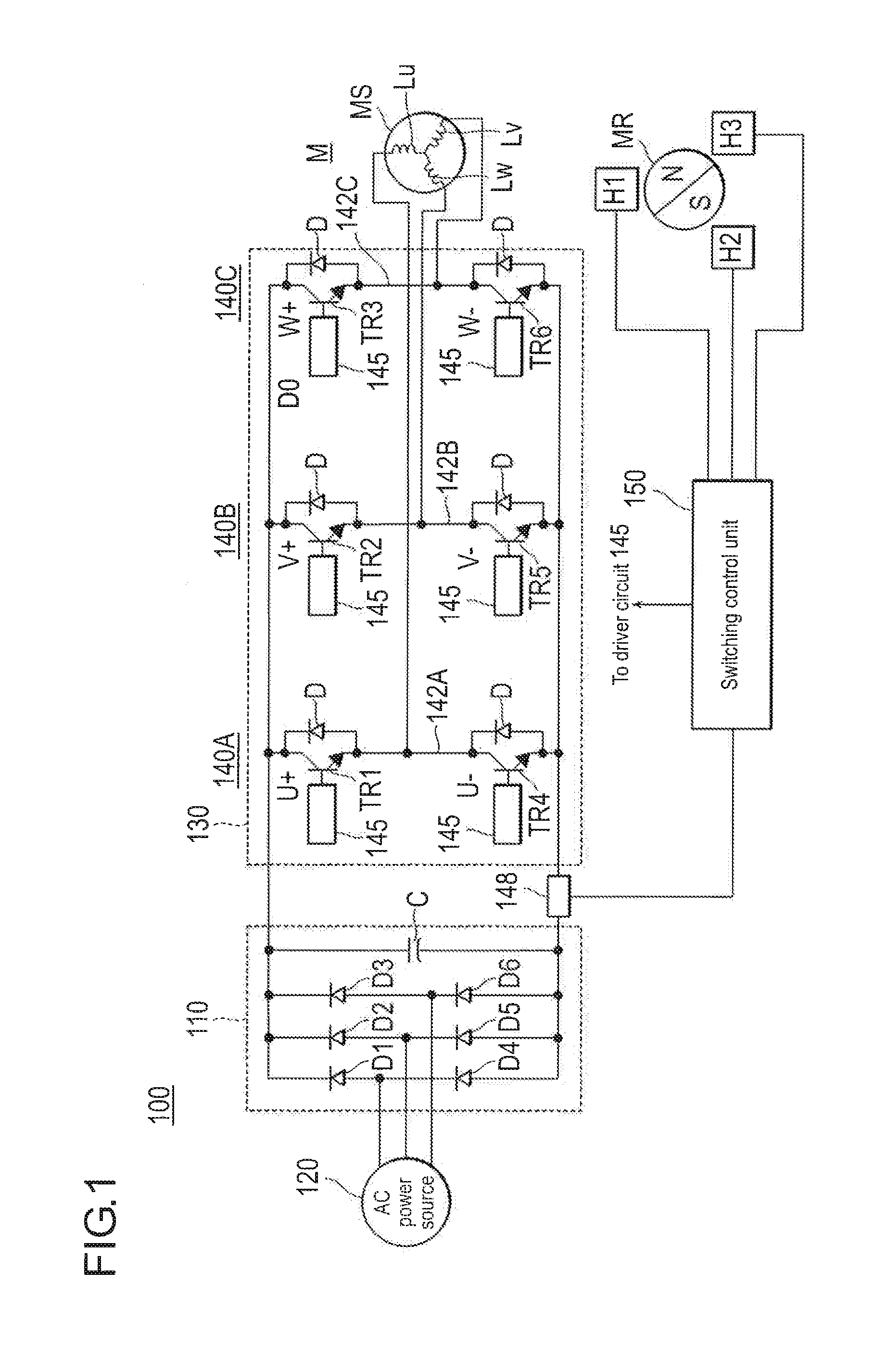
[0033]FIG. 1 is a schematic diagram showing a configuration of the fan motor control unit according to the embodiment.

[0034]The fan motor control unit 100 includes a rectifier circuit 110 having a smoothing capacitor C, and an inverter circuit 130 connected to the fan motor M.

[0035]The rectifier circuit 110 includes, as shown in FIG. 1, six diodes D1 to D6 bridge-connected to each other, and the six diodes D1 to D6 each perform full-wave rectification of the current from an AC power source (three-phase) 120. The current fully rectified by the six diodes D1 to D6 is smoothed by the smoothing capacitor C, so that the ripple of the DC obtained through the full-wave rectification is suppressed. The rectifier circuit 110 serves as the power source for the fan motor M.

[0036]An inverter circuit 130 that serves as the switching unit is conne...


PUM


Abstract

A fan motor control unit includes sensor units that each detect a rotational position of the fan motor, a switching unit that selectively connects each of stator coils of the fan motor to a rectifier circuit, a current sensor that detects a current flowing in the fan motor, and a switching control unit that advances, in the case where the current detected by the current sensor exceeds a threshold, a energization timing from the rectifier circuit to the stator coils with respect to the energization timing applied while the current detected by the current sensor is lower than the threshold, on the basis of the rotational position detected by the sensor units.

Description

BACKGROUND[0001]1. Technical Field[0002]The present invention relates to a fan motor control unit that suppresses degradation in air volume characteristic and an increase in power loss, despite an increase in load imposed on the fan motor.[0003]2. Description of Related Art[0004]Brushless motors have thus far been employed for use as fan motor, because the rotation speed can be controlled over a wide range. The brushless motor includes, for example as disclosed in Japanese Unexamined Patent Application Publication No. 2006-180608, a plurality of Hall elements to detect the rotational position of the rotor according to signals outputted by the Hall elements.[0005]Energization timing for the stator coil in the brushless motor is set in advance with respect to each of the rotational positions of the rotor. Here, the energization timing refers to the timing at which the stator coil is connected to the power source.[0006]In existing fan motor control units, however, the energization timi...

Claims


Application Information

Patent Timeline
IPC IPC(8): F04D27/00H02P6/06H02P6/08H02P6/15H02P6/16H02P6/28
CPCF04D27/001F04D27/008H02P6/15
Inventor MURAMATSU, YOTODA, TAKAHISANISHIMAKI, KENTA
Owner SANYO DENKI CO LTD
Why Eureka
Try Eureka