Compact Load Balanced Switching Structures for Packet Based Communication Networks

Inactive Publication Date: 2008-10-30
HALL TREVOR DR
View PDF18 Cites 21 Cited by
  • Summary
  • Abstract
  • Description
  • Claims
  • Application Information

AI Technical Summary

Benefits of technology

[0014]As a result the switching node can meet all of the demands of the network provider in terms of quality of service, flexibility of provisioning to a users varied demands for services, and prioritizing packet data switching based upon predetermined pri

Problems solved by technology

For example, when downloading most information via the Internet, a small delay is acceptable for text and photographs but not for streamed video unless sufficient memory buffer exists.
Within this mesh are a limited number of optical switches which generally provide protection switching and relatively slow allocation of bandwidth to accommodate demand.
But the demands from users for increased services, increased bandwidth and flexible services are causing the network operators to seek a

Method used


Image

  • Compact Load Balanced Switching Structures for Packet Based Communication Networks
  • Compact Load Balanced Switching Structures for Packet Based Communication Networks
  • Compact Load Balanced Switching Structures for Packet Based Communication Networks

Examples


second embodiment

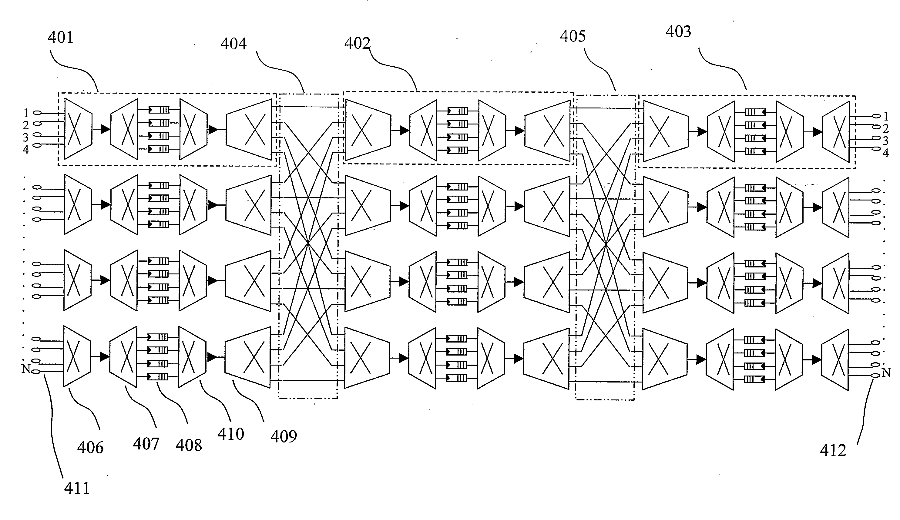
[0034]Referring to FIG. 4A, a simplified architectural diagram of the invention is shown in the form of a compact load balanced three stage Clos network wherein the Clos stages operate at a same line data rate as an input port and an output port. Here a packet of data is incident at one of N input ports 411 of a packet switching node. A header of the packet of data is read and communicated to a packet switching node controller (not shown) which defines a routing of the packet through the node. The packet switching node controller communicates the routing data to a first stage switch matrix 401 comprising a first concentrator switch 406, a first memory switch element comprising a first distribution switch 407, a plurality of first memory queues 408 and a first concentrator switch 409.

[0035]From the output port of the first concentrator switch 409, the packet of data is routed to a second distribution switch 410 which feeds the packet of data forward to a first perfect shuffle network...

third embodiment

[0041]Now referring to FIG. 5, a simplified architectural diagram of the invention is shown in the form of a compact load balanced three stage Clos network wherein the Clos stages operate at half the data rate of an input port and an output port. A packet of data arrives at one of N input ports 512 of a packet switching node. A header of the packet of data is read and communicated to a packet switching node controller (not shown), which determines routing for the packet through the node. The packet switching node controller communicates routing data to a first stage switch matrix 501, which comprises a first concentrator switch 506, a first memory switch element comprising a first distribution switch 507, a plurality of memory queues 508 and a first concentrator switch 509.

[0042]From the output port of the first concentrator switch 509, the packet of data is routed to a second distribution switch 510 which feeds the packet of data forward to a first perfect shuffle network 504. In u...


PUM


Abstract

A switching node is disclosed for the routing of packetized data employing a multi-stage packet based routing fabric combined with a plurality of memory switches employing memory queues. The switching node allowing reduced throughput delays, dynamic provisioning of bandwidth and packet prioritization.

Description

FIELD OF THE INVENTION[0001]The invention relates to the field of communications and more particularly to a scaleable architecture for packet based communication networking.BACKGROUND OF THE INVENTION[0002]Telecommunications networks have evolved from the earliest networks having few users with plain old telephone service (POTS) to networks in operation today interconnecting hundreds of millions of users with a wide variety of services including for example telephony, Internet, streaming video, and MPEG music. Central to these networks is the requirement for a switching fabric allowing different users to be connected either together or to a service provider. Supporting an increase in a number of users, connections and bandwidth are networks based upon segmentation, transmission, routing, detection and reconstruction of a signal. The segmentation results in a message being divided into segments—referred to as packets, and such networks being packet switched networks.[0003]From a view...

Claims


Application Information

Patent Timeline
IPC IPC(8): H04L12/56
CPCH04L47/125H04L49/101H04L49/3018H04L49/90
Inventor HALL, TREVORPAREDES, SOFIATAEBI, SAREH
Owner HALL TREVOR DR
Why Eureka
Try Eureka