
Control apparatus and control method for negative pressure generating apparatus

a technology of control apparatus and negative pressure generating apparatus, which is applied in the direction of process and machine control, combustion-air/fuel-air treatment, instruments, etc., can solve the problem of adversely affecting the driving ability of the vehicl

Inactive Publication Date: 2008-10-30
TOYOTA JIDOSHA KK
View PDF4 Cites 36 Cited by
  • Summary
  • Abstract
  • Description
  • Claims
  • Application Information

AI Technical Summary

Benefits of technology

[0011]The invention provides a control apparatus and a control method for a negative pressure generating apparatus, which prevent an ejector from being unnecessarily operated when a vehicle is decelerated.
[0013]With the above-described configuration, the ejector is prohibited from being operated when the vehicle is transiently decelerated. Therefore, it is possible to prevent the ejector from being unnecessarily operated when the vehicle is decelerated. This suppresses a decrease in durability of the state change device, and reduces the possibility that foreign matter enters the negative pressure generating apparatus. The ejector is generally provided in a bypass passage that bypasses a throttle valve. When the ejector functions, the amount of air taken into the internal combustion engine is increased by an amount of air flowing through the ejector. However, with the above-described configuration, it is possible to avoid a situation where the ejector is unnecessarily operated, and therefore, the amount of air taken into the internal combustion engine is changed, and thus, drivability of the vehicle is adversely affected.
[0015]According to the invention, it is possible to provide the control apparatus and the control method for the negative pressure generating apparatus, which prevent the ejector from being unnecessarily operated when the vehicle is decelerated.

Problems solved by technology

However, with the above-described configuration, it is possible to avoid a situation where the ejector is unnecessarily operated, and therefore, the amount of air taken into the internal combustion engine is changed, and thus, drivability of the vehicle is adversely affected.

Method used


Image

  • Control apparatus and control method for negative pressure generating apparatus
  • Control apparatus and control method for negative pressure generating apparatus
  • Control apparatus and control method for negative pressure generating apparatus

Examples


Embodiment Construction

[0021]Hereinafter, an embodiment of the invention will be described in detail with reference to the drawings.

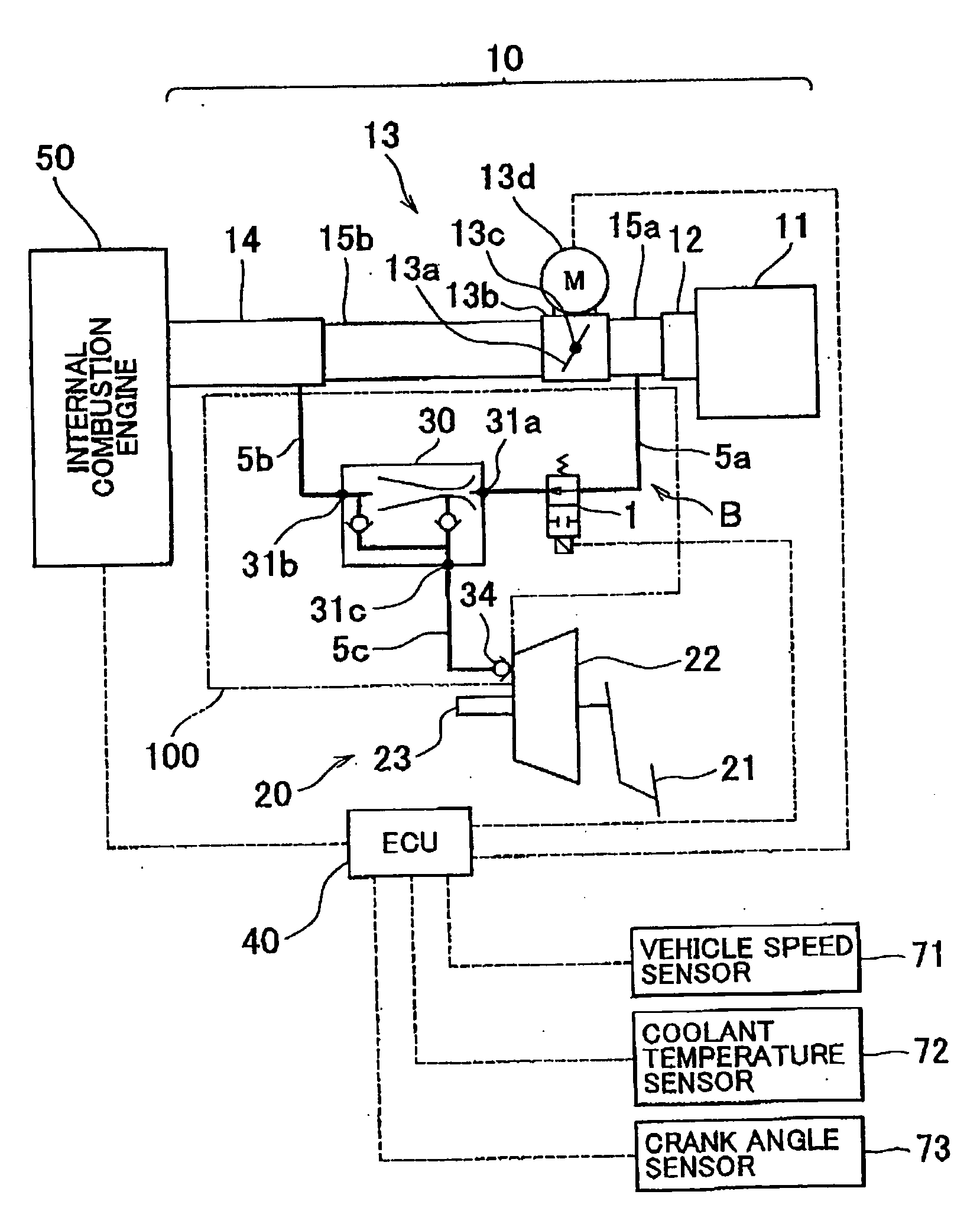
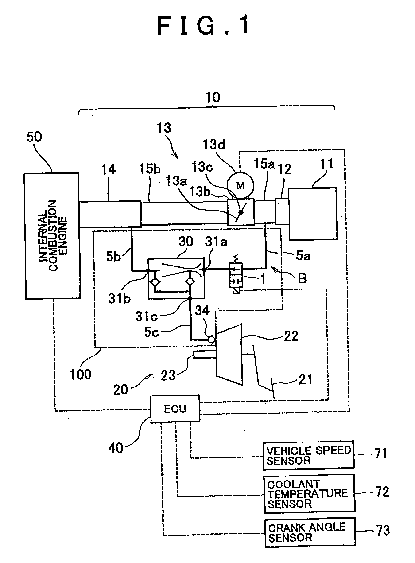
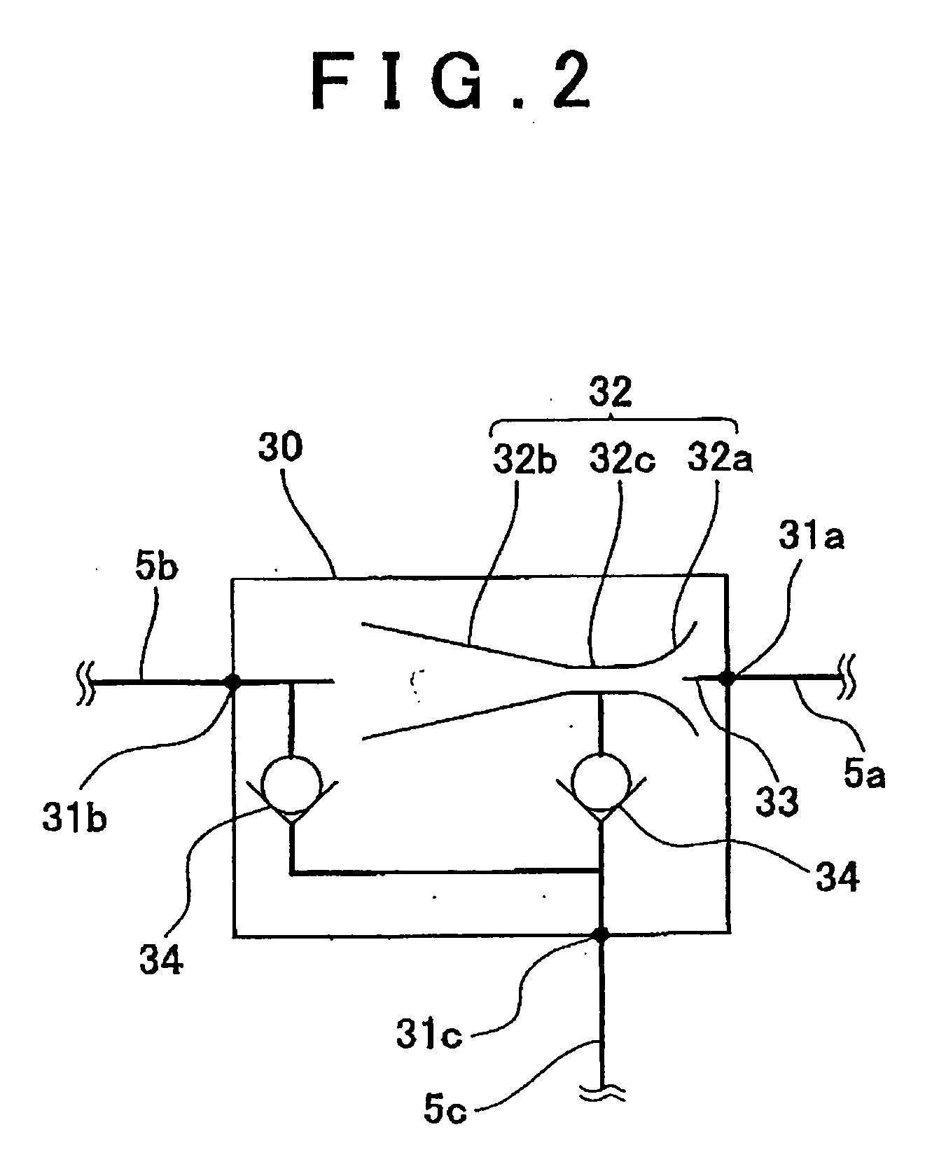
[0022]FIG. 1 is a schematic diagram showing a control apparatus for a negative pressure generating apparatus according to an embodiment of the invention, along with a negative pressure generating apparatus 100. The control apparatus is implemented by an ECU (Electronic Control Unit) 40. Components shown in FIG. 1, which include an internal combustion engine 50, are provided in a vehicle (not shown). An intake system 10 for the internal combustion engine 50 includes an air cleaner 11, an airflow meter 12, an electric throttle 13, an intake manifold 14, intake ports (not shown) connected to cylinders (not shown) of the internal combustion engine 50, and members (for example, intake pipes 15a and 15b) that are appropriately provided among the components. The air cleaner 11 filters intake air supplied to the cylinders of the internal combustion engine 50. The atmospheric air flow...


PUM


Abstract

A control apparatus for a negative pressure generating apparatus, includes an ejector that generates a negative pressure whose magnitude is larger than that of a negative pressure to be taken from an intake passage in an intake system for an internal combustion engine provided in a vehicle; a state change device that makes the ejector function or stop functioning; and a prohibition control device that prohibits the state change device from making the ejector function, when the vehicle is transiently decelerated.

Description

INCORPORATION BY REFERENCE[0001]The disclosure of Japanese Patent Application No. 2007-117638 filed on Apr. 26, 2007 including the specification, drawings and abstract is incorporated herein by reference in its entirety.BACKGROUND OF THE INVENTION[0002]1. Field of the Invention[0003]The invention relates to a control apparatus and a control method for a negative pressure generating apparatus. More specifically, the invention relates to a control apparatus and a control method for a negative pressure generating apparatus, which make an ejector function according to a magnitude of a negative pressure to be taken from an intake passage.[0004]2. Description of the Related Art[0005]In a vehicle, an ejector is used to supply a negative pressure whose magnitude is larger than that of a negative pressure to be taken from an intake passage (for example, an intake manifold or a surge tank) in an intake system for an internal combustion engine, to a negative pressure operating device such as a...

Claims


Application Information

Patent Timeline
Patent Type & Authority Applications(United States)
IPC IPC(8): F04F5/48
CPCB60T17/02F02M35/10229F04F5/52
Inventor HIROOKA, SHIGEMASA
Owner TOYOTA JIDOSHA KK
Learn More