
Temperature Controlling Method for Substrate Processing System and Substrate Processing System

a technology of substrate processing and temperature control, which is applied in the direction of cooling fluid circulation, lighting and heating apparatus, domestic cooling apparatus, etc., can solve the problems of high cost of laying pipes, excessive load on chillers and pumps, and high energy loss of chillers and pumps during operation, so as to save piping space, reduce energy, and cost

Inactive Publication Date: 2008-11-06
TOKYO ELECTRON LTD
View PDF3 Cites 43 Cited by
  • Summary
  • Abstract
  • Description
  • Claims
  • Application Information

AI Technical Summary

Benefits of technology

[0007]In view of the aforementioned drawbacks in the prior art, the present invention was accomplished. In a substrate processing system comprising a plurality of substrate processing units such as wafer processing units, an object of the invention is to save piping space and to realize temperature control with decreased energy at lower cost.

Problems solved by technology

Furthermore, the cost for laying the pipes has been high.
Moreover, a powerful pump is needed to feed the cooling medium from the chiller to the wafer processing unit on the floor through the big, long pipe, and such a pump has been a cause of excessively heavy loading on the chiller and the pump.
For this reason, the energy loss of the chiller and the pump during operation has been great, and the energy cost, such as power consumption, has been increasing.

Method used


Image

  • Temperature Controlling Method for Substrate Processing System and Substrate Processing System
  • Temperature Controlling Method for Substrate Processing System and Substrate Processing System
  • Temperature Controlling Method for Substrate Processing System and Substrate Processing System

Examples


Embodiment Construction

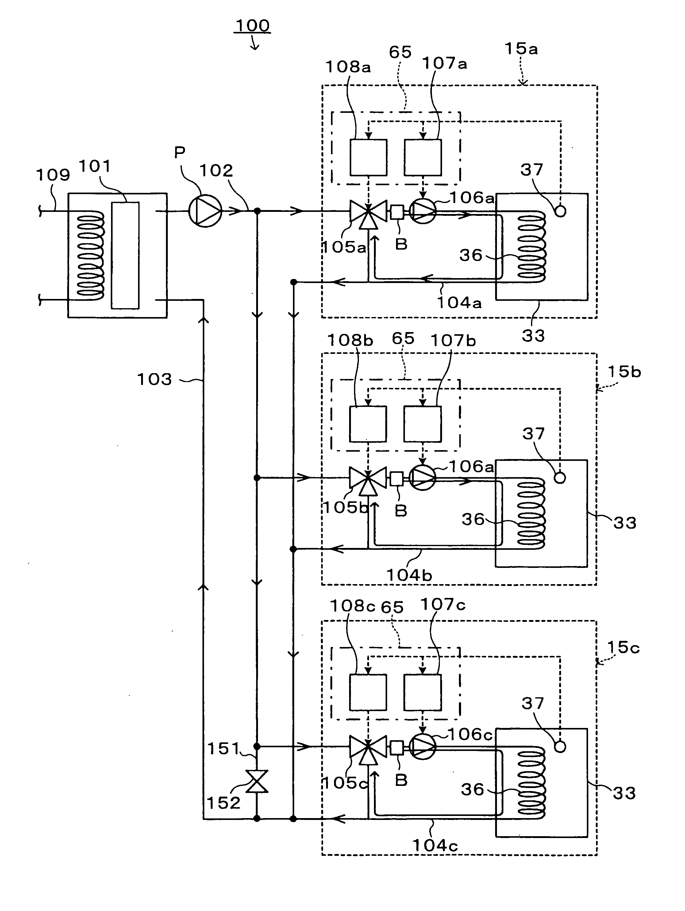
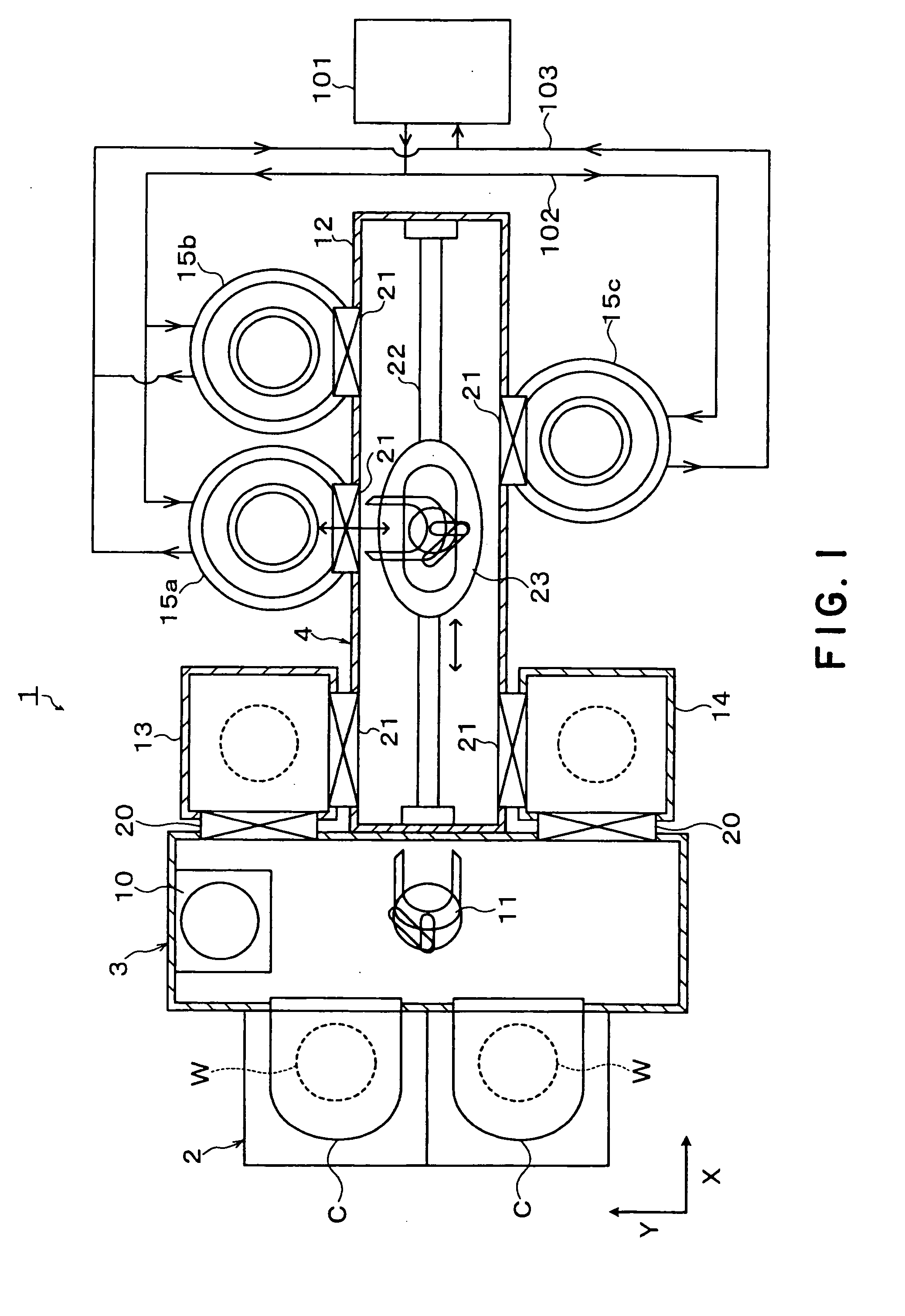
[0052]A preferred embodiment of the present invention will be described hereinafter. FIG. 1 is a plane view schematically showing the structure of a substrate processing system 1 in which a temperature controller according to this embodiment is used.

[0053]For example, the substrate processing system 1 is composed of a cassette-holding table 2, a carrier vessel 3, and a vacuum processing unit 4 that are connected linearly in the X direction (the horizontal direction in FIG. 1). On the cassette-holding table 2 can be placed an airtight cassette C such as an FOUP (Front Opening Unified Pod) in which a pile of twenty-five wafers W, for example, is contained. On the cassette-holding table 2, two cassettes C, for example, can be placed side by side in the Y direction (the vertical direction in FIG. 1).

[0054]The carrier vessel 3 is provided with an alignment stage 10 for positioning a wafer W taken out of the cassette C, and a wafer carrier 11 for carrying the wafer W, having a multiple jo...


PUM

PropertyMeasurementUnit
Temperatureaaaaaaaaaa

Abstract

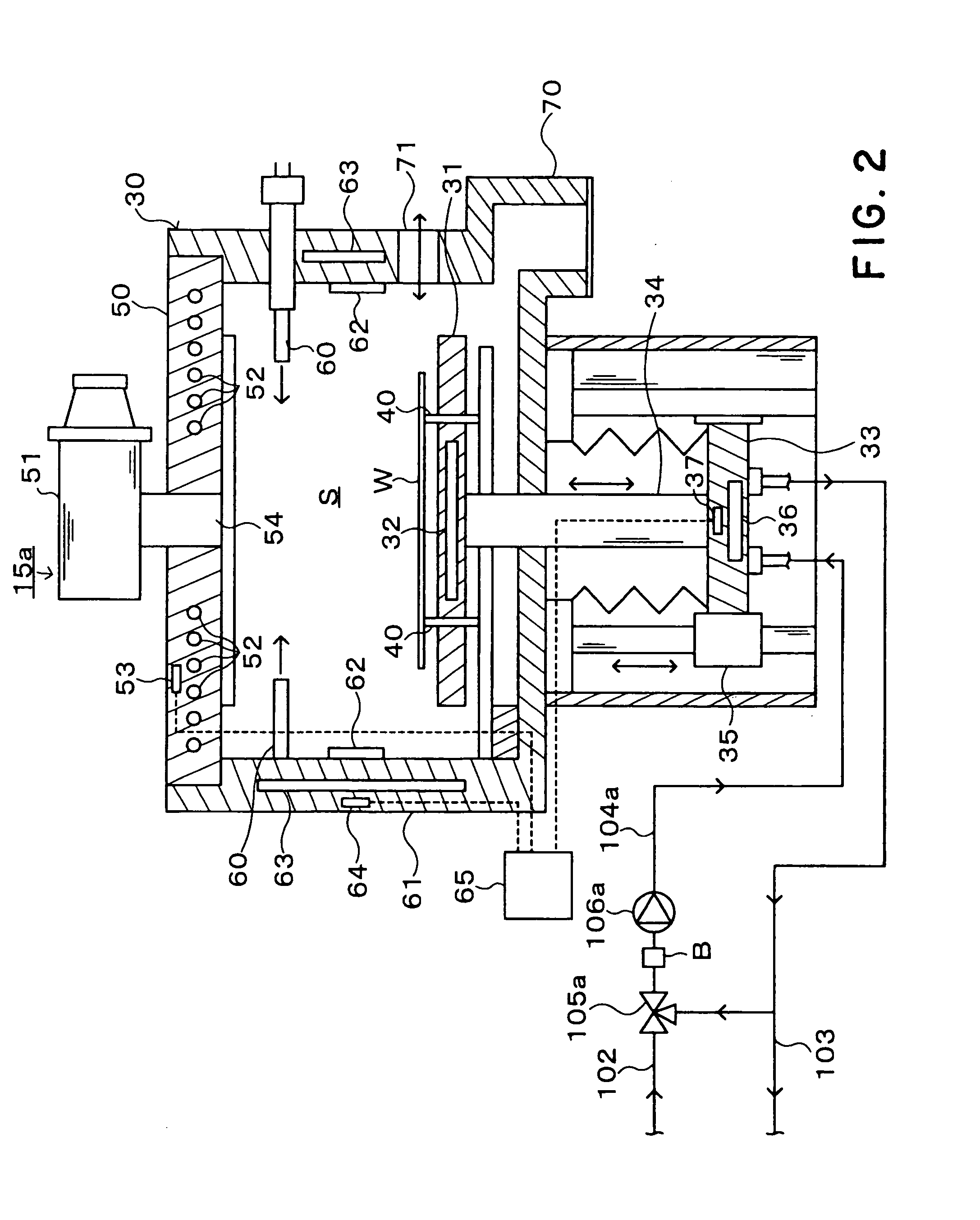
A substrate processing system comprises a plurality of CVD processing units (15a-15c) and one refrigerator (101). A supply line (102) for supplying a cooling medium from the refrigerator to the CVD processing units, and a feedback line (103) for feeding the cooling medium back to the refrigerator from the processing units are laid in the system. The cooling medium from the refrigerator is thus distributively fed to the processing units. Circuits (104a-104c) are laid out in rod stages (33), objects of temperature control, in the respective processing units. Each circuit is connected to the supply line and to the feedback line. The cooling medium is circulated around the circuits to control the temperatures of the rod stages stably. When the temperature of the rod stage rises, the cooling medium at a low temperature is taken in the circuit from the supply line to cool the rod stage.

Description

BACKGROUND OF THE INVENTION[0001]1. Field of the Invention[0002]The present invention relates to a method of controlling the temperatures of two or more substrate processing units that constitute a substrate processing system, and to a substrate processing system comprising a plurality of substrate processing units whose temperatures are controllable.[0003]2. Background Art[0004]In a process for manufacturing a semiconductor device or the like, there is conducted plasma processing in which a wafer is processed with plasma, such as film deposition processing or etching processing.[0005]Such plasma processing is usually conducted in two or more wafer processing units installed in a factory. The plasma processing is conducted in processing vessels in the wafer processing units under high-temperature conditions, and, in order to keep the wafer processing conditions constant, it is necessary to hold the inside of each processing vessel at a constant temperature during processing. Therefo...

Claims


Application Information

Patent Timeline
IPC IPC(8): G05D23/19F25D17/02H01L21/205C23C16/46F25D9/00F25D13/00H01L21/00H01L21/3065
CPCC23C16/4411C23C16/46C23C16/463F25B2700/21F25D17/02F25D2400/02H01J37/32522H01J37/32724H01J2237/2001H01L21/67248
Inventor NOZAWA, TOSHIHISAKOTANI, KOJI
Owner TOKYO ELECTRON LTD
Learn More