Rocker arm for valve actuation

a rocker arm and valve technology, applied in valve arrangements, machines/engines, mechanical equipment, etc., can solve the problems of high amplitude vibration force to react on rocker arms and valve system components, engine block and cylinder head castings are complicated with structure, and achieve the effect of increasing airflow into the cylinder

Inactive Publication Date: 2008-11-06
WEAVER ROBERT R
View PDF16 Cites 6 Cited by
  • Summary
  • Abstract
  • Description
  • Claims
  • Application Information

AI Technical Summary

Benefits of technology

[0013]Preferably, a spring rate function is developed for rocker arm beam portion on either side of the pivot portion. Initiating defection of rocker arm portion late in the valve opening sequence, storing energy like a spring, released as the cam opening is completed, in effect lofting the valve, increasing airflow into the cylinder. This is a potential benefit to valve actuation in certain applications.
[0014]Preferably, there is provision for setting valve lash clearance by means of a shim and / or spacer; eliminating the inertia mass of a screw adjustment fitting to the rocker arm body making connection with the push rod. Screw adjustments remain the most common alternative system in general use.

Problems solved by technology

These high engine speeds cause very high inertia forces and high amplitude vibration forces to react on rocker arms and valve system components.
This condition results because engine block and cylinder head castings are complicated with structure in the path areas where push rods operate.
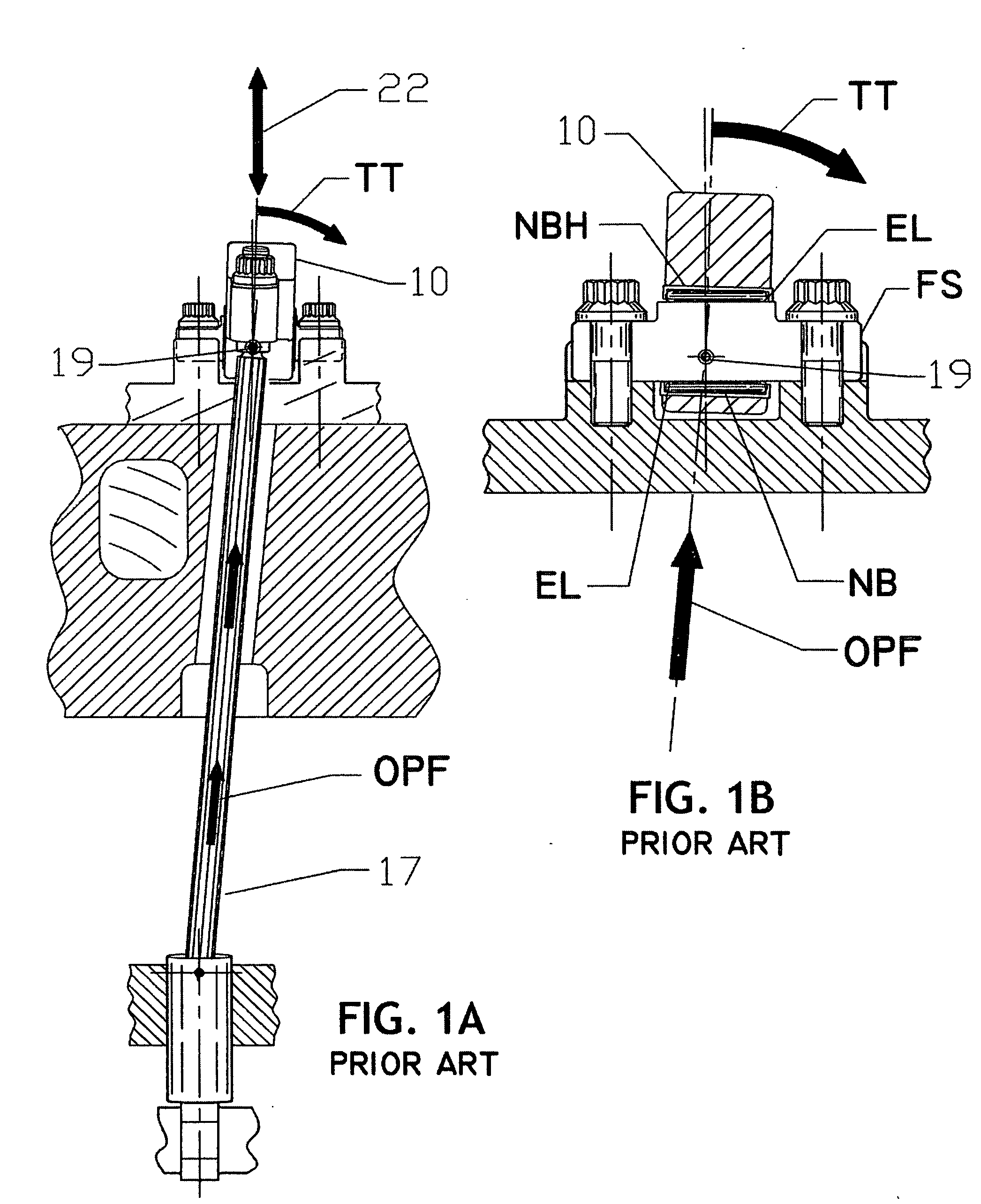
The centered, narrow bearing width is not sufficient to stabilize and distribute high impact force.
Conditions occur where bearing edge loading cause material to yield a slight amount, enough to increase bearing radial clearance, allowing excess looseness, known to increase vibration amplitude, inducing discord of valve timing lift and performance.
Indeed, crack failures are common in the beam area near the push rod connection.
These described conditions require precautionary and costly rocker arm replacement after a short service time in performance engines.
Once initiated, spring surge creates valve movement disarray and failures.

Method used


Image

  • Rocker arm for valve actuation
  • Rocker arm for valve actuation
  • Rocker arm for valve actuation

Examples


Embodiment Construction

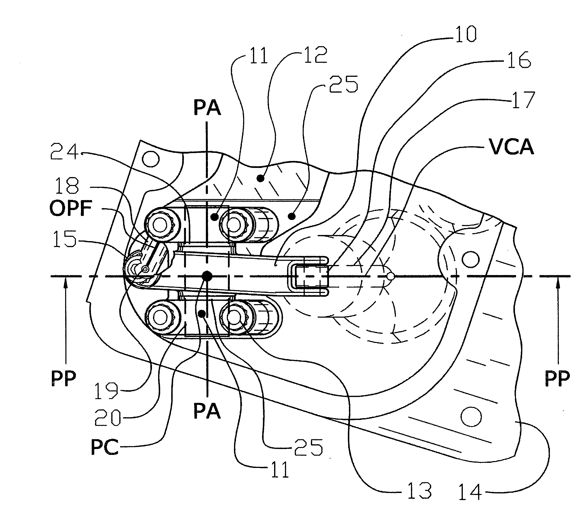
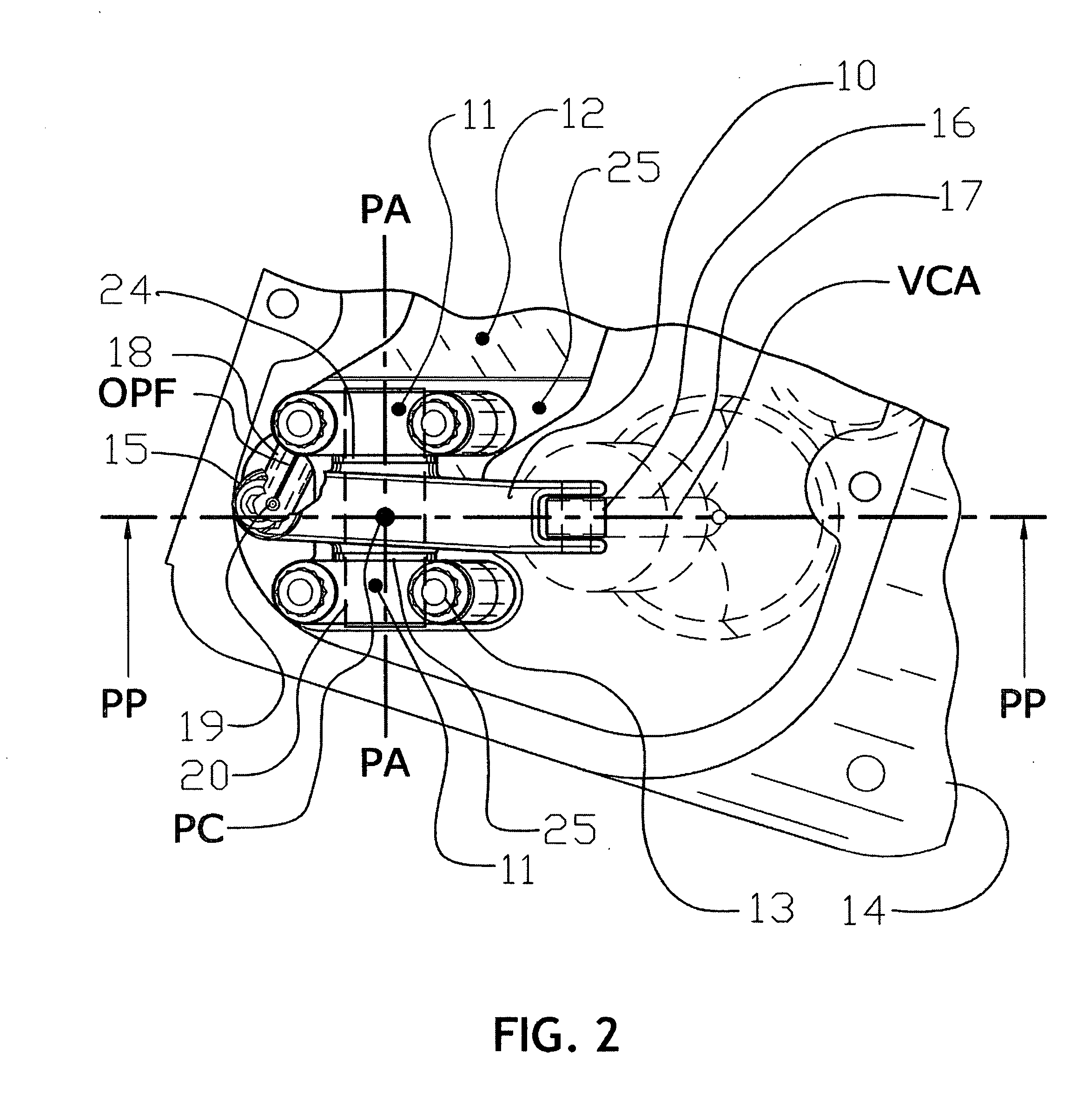
[0030]The improved system embodies a rocker arm beam having journals, (cylindrical pivot projections, one each side), extending from each side of the rocker arm body making a single whole structure, supported and pivoting in outboard bearings and bearing mounts to guide the pivot motion of the rocker arm and journal as a whole. The improved rocker arm embodiment with journals and outboard bearings embodies a widely spaced dual bearing support, thus eliminating common installation of a pivot bearing or bearings centered within the rocker arm beam body. This improvement provides wide stable resistance to rocker beam deforming torsional forces. The improved stability provides a rocker arm pivot system having accurate and precise valve actuation. Improving valve system stability and precision leads to higher potential engine speed and improved engine performance and reduced or eliminated unwanted valve train excitation caused by vibration amplitude excesses.

[0031]A detailed description ...


PUM


Abstract

The present invention provides an improved rocker arm system for actuating poppet valves in high performance internal combustion engines. The rocker arm provides journals extending from each side fitted to outboard bearing mounts to guide the motion of the rocker arm.

Description

CROSS-REFERENCE TO RELATED PATENT APPLICATIONS[0001]This is a U.S. non-provisional application relating to and claiming the benefit of U.S. Provisional Patent Application Ser. No. 60 / 635,468, filed Dec. 13, 2004 and is a Continuation-in-part of U.S. patent application Ser. No. 11 / 302,181 filed Dec. 12, 2005.BACKGROUND OF THE INVENTION[0002]1. Field of the Invention[0003]The present invention relates to the field of internal combustion engines, high performance and conventional manufactured engines in general use, pertaining to poppet valve operating systems, particularly rocker arm systems for valve actuation pivoting on a shaft, the rocker arm being actuated by push rods and a camshaft.[0004]2. Description of Background Information[0005]Internal combustion engines, including high performance engines and conventionally manufactured engines, having poppet valve systems actuated by rocker arms and push rods that operate at high engine speeds or having high dynamic forces within the va...

Claims


Application Information

Patent Timeline
Patent Type & Authority Applications(United States)
IPC IPC(8): F01L1/18
CPCF01L1/181F01L1/182
Inventor WEAVER, ROBERT R.
Owner WEAVER ROBERT R
Why Eureka
Try Eureka