Method and apparatus for producing an indication of solar panel condition

a technology for solar panels and indicators, applied in the field of solar panels, can solve the problems of dirt and debris contamination, and not always being able to determine whether a reduction in power output is possible,

Active Publication Date: 2008-11-06
SCHNEIDER ELECTRIC SOLAR INVERTERS USA
View PDF2 Cites 70 Cited by
  • Summary
  • Abstract
  • Description
  • Claims
  • Application Information

AI Technical Summary

Benefits of technology

[0068]The processor circuit may be operably configured to cause the warning signal to be produced when the power signal represents an actual power output less than the power estimate.
[0069]The processo...

Problems solved by technology

Being outdoors they are also exposed to contamination by dirt and debris such as dust, sticks, leaves, or snow for example.
In general it is not always possible to determine whether a reduction in power ou...

Method used


Image

  • Method and apparatus for producing an indication of solar panel condition
  • Method and apparatus for producing an indication of solar panel condition
  • Method and apparatus for producing an indication of solar panel condition

Examples


first embodiment

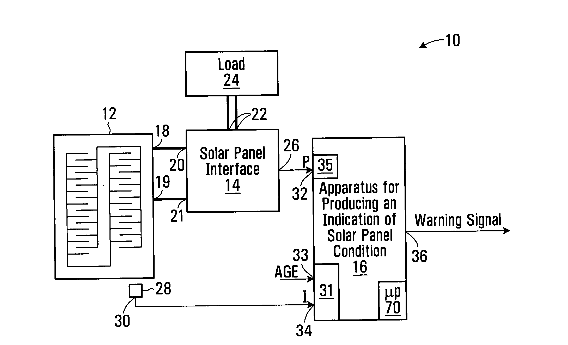
[0088]Referring to FIG. 1, a solar power generation system according to the invention is shown generally at 10. The system 10 includes a solar panel 12, a solar panel interface 14, and an apparatus 16 for producing an indication of solar panel condition.

[0089]The solar panel 12 may include a plurality of photovoltaic cells that are operable to convert light energy into electrical energy. The solar panel 12 includes a pair of output terminals 18 and 19, which facilitate connecting the solar panel to a load or an interface, for example.

[0090]The solar panel interface 14 includes input terminals 20 and 21 for receiving the output power from the respective output terminals 18 and 19 of the solar panel 12. The solar panel interface 14 also includes a pair of output terminals 22 for supplying output power to a load 24. The solar panel interface 14 is generally operable to receive input power at the terminals 20 and 21 and to convert the input power into an output power at the terminals 22...

second embodiment

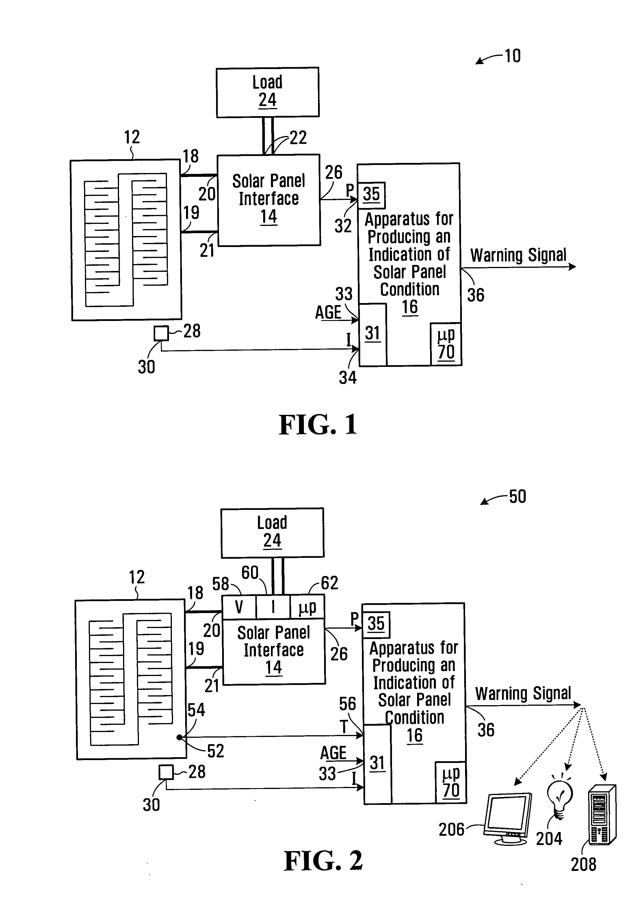
[0095]Referring to FIG. 2, a solar power generation system is shown generally at 50. The system 50 includes the solar panel 12, the solar panel interface 14, and the apparatus 16, as shown in FIG. 1. In this embodiment the solar panel 12 further includes a temperature sensor 52 operably configured to sense a temperature of the solar panel and having an output 54 for producing a temperature signal representing a temperature of the solar panel. In this embodiment the operating condition receiver 31 also includes an input 56 for receiving the temperature signal from the output 54 of the temperature sensor 52. The irradiance measuring apparatus 28 and / or the temperature sensor 52 may be wireless devices, for example.

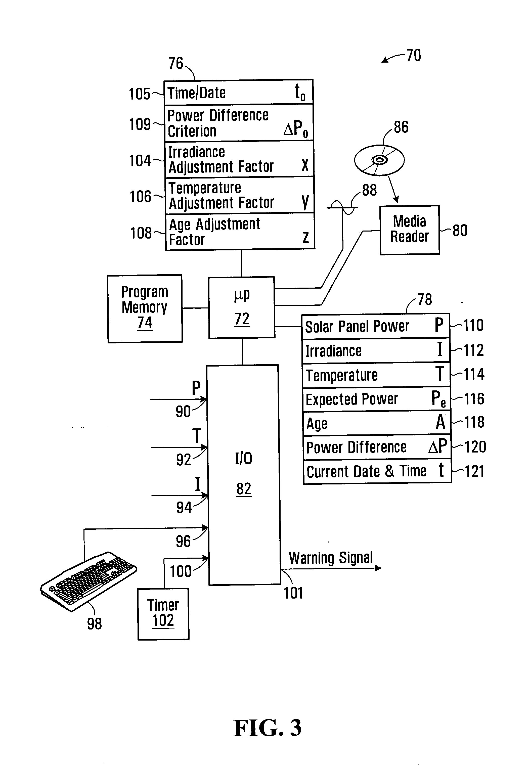
[0096]In this embodiment, the processor circuit 70 is operably configured to produce a power estimate in response to the operating condition signals including the temperature signal, the age signal, the irradiance signal, a temperature adjustment factor, an irradiance adjust...


PUM


Abstract

A method and apparatus for producing an indication of solar panel condition is disclosed. The method involves receiving operating condition signals including an irradiance signal representing electromagnetic radiation received by the solar panel, and an age signal representing age of the solar panel. The method also involves receiving a power signal representing actual power output from the solar panel and producing a power estimate in response to the operating condition signals and irradiance and age adjustment factors. The power estimate represents an expected power output from the solar panel and the adjustment factors are for adjusting the irradiance signal and the age signal respectively. The method further involves causing a warning signal to be generated in response to a difference between the power signal and the power estimate.

Description

BACKGROUND OF THE INVENTION[0001]1. Field of Invention[0002]This invention relates generally to solar panels, and more particularly to methods and apparatus for monitoring the condition of solar panels.[0003]2. Description of Related Art[0004]Solar panels are used in solar power generation systems to produce electrical power. Solar panels generally produce direct current (DC) power which may be used to charge a bank of batteries. Alternatively, the DC power may be supplied to a power converter that converts the DC power into AC power suitable for supplying an AC power grid, for example.[0005]Solar panels are generally mounted outdoors for exposure to the sun's radiation. Being outdoors they are also exposed to contamination by dirt and debris such as dust, sticks, leaves, or snow for example. Such contamination may not physically damage the solar panels, but can cause a reduction in electrical power output for a given insolation as it can reduce the amount of radiation that is able ...

Claims


Application Information

Patent Timeline
IPC IPC(8): G01J1/44
CPCH01L31/02021H02S50/10Y02E10/50
Inventor THOMPSON, CHRISTOPHER SCOTT
Owner SCHNEIDER ELECTRIC SOLAR INVERTERS USA
Why Eureka
Try Eureka