Hydraulic System for a Vehicle Suspension

a hydraulic system and vehicle technology, applied in the direction of suspensions, interconnection systems, suspensions, etc., can solve the problems of significant ride comfort limitations, seat friction, and change in ride height, and achieve the effect of removing the roll stiffness of the hydraulic system and zero warp stiffness

Active Publication Date: 2008-11-06
KINEHTIK PTI LTD
View PDF8 Cites 45 Cited by
  • Summary
  • Abstract
  • Description
  • Claims
  • Application Information

AI Technical Summary

Benefits of technology

[0015]The hydraulic suspension system according to one or more forms of the present invention allows for independent tuning and configuration of suspension parameters including roll stiffness, roll moment distribution, roll damping and heave damping. This enables optimisation of as many of these suspension parameters as required.
[0016]The vehicle may preferably be primarily supported by the resilient vehicle support means. The advantages of the hydraulic system providing little or no support of the vehicle body are numerous: the operating pressure of the system can be reduced which reduces seal friction and improves ride comfort; the operating pressure of each of the four fluid volumes can be common which reduces the pressure differential across piston seals and therefore reduces control complexity, friction, improves ride comfort and reduces any potential leakage across piston seals between the four fluid volumes; the rod diameter of each ram can be much reduced, which provides a reduction in seal friction and improves ride comfort; the reduction in rod diameter permits a reduction in cylinder bore diameter which reduces fluid mass acceleration effects and improves ride comfort; and the hydraulic system can be designed to supply a portion of the support for one or both ends of the vehicle without providing a warp stiffness and can be used to compensate for loads applied to the vehicle. Indeed if the rear ram rods are of larger diameter than the front ram rods then as a load is added towards the rear of the vehicle, compressing the resilient vehicle support means, the pressure may be increased in the hydraulic system, providing more load compensation at the rear. At the same time if the roll moment distribution of the resilient vehicle support means is towards the front of the vehicle, and the roll moment distribution of the hydraulic system is less front biased, then as the pressure and stiffness of the hydraulic system is increased, the vehicle total suspension roll moment distribution may move rearwards to better match the requirement with a rearward positioned load.
[0018]The vehicle support means for at least one end of the vehicle may include first support means for providing support for at least a portion of the load on the vehicle, the first support means providing a roll stiffness.
[0019]The vehicle support means for at least one end of the vehicle may include second support means for providing support for at least a portion of the load on the vehicle, the second support means providing substantially zero roll stiffness.
[0024]Damping means may be provided for damping the flow of fluid into and / or out of at least one chamber of each wheel ram.
[0033]Additionally or alternatively, at least one valve may be provided between the front fluid volumes and / or at least one valve may be provided between the rear fluid volumes for removing the roll stiffness of the hydraulic system.

Problems solved by technology

Since this system supports the vehicle, the pressures in the four fluid volumes must be high, or the rod diameters large to provide the support force for the vehicle, which leads to seal friction and significant ride comfort limitations.
Furthermore, as the temperature changes, the volumes of gas and fluid in the system cause ride height changes, requiring a costly high pressure fluid supply and control system.
Also, the pressure in each of the four fluid volumes must be individually correct to provide the required support at each wheel, so the pressures are usually different, leading to control complexity, leakage past the piston seals between the fluid volumes and increase in piston seal friction.
Also, as the six volumes in the system can, in some load conditions, all be at different pressures, there is the possibility for fluid to leak across seals, which also requires fluid volume adjustments to be made to maintain the correct vehicle attitude.
This requires a high pressure fluid source, sensors, control electronics and valves, making the cost of the system relatively high for a passive system.
As these hydraulic systems provide support of the vehicle they have similar disadvantages to the applicant's aforementioned U.S. Pat. No. 6,270,098.
As the system does not provide significant heave stiffness, separate support springs are required.
The roll moment distribution required of the hydraulic system drives the selection of wheel ram sizes and can lead to compromises in peak damping force.
However this system does not provide significant stiffness in any mode, so in addition to the need for support springs, generally anti-roll bars will be required for a good balance between bounce and roll stiffness rates front and rear.
Additionally, as the wheel rams are effectively single acting (having only one fluid port) the amount of damping that the device can provide is limited.
There are improvements made to the system to combat this problem, which can be found in Japanese patent office publication number 11291737, but these add to the complexity of the system by providing more plumbing and spool valves.

Method used


Image

  • Hydraulic System for a Vehicle Suspension
  • Hydraulic System for a Vehicle Suspension
  • Hydraulic System for a Vehicle Suspension

Examples


Embodiment Construction

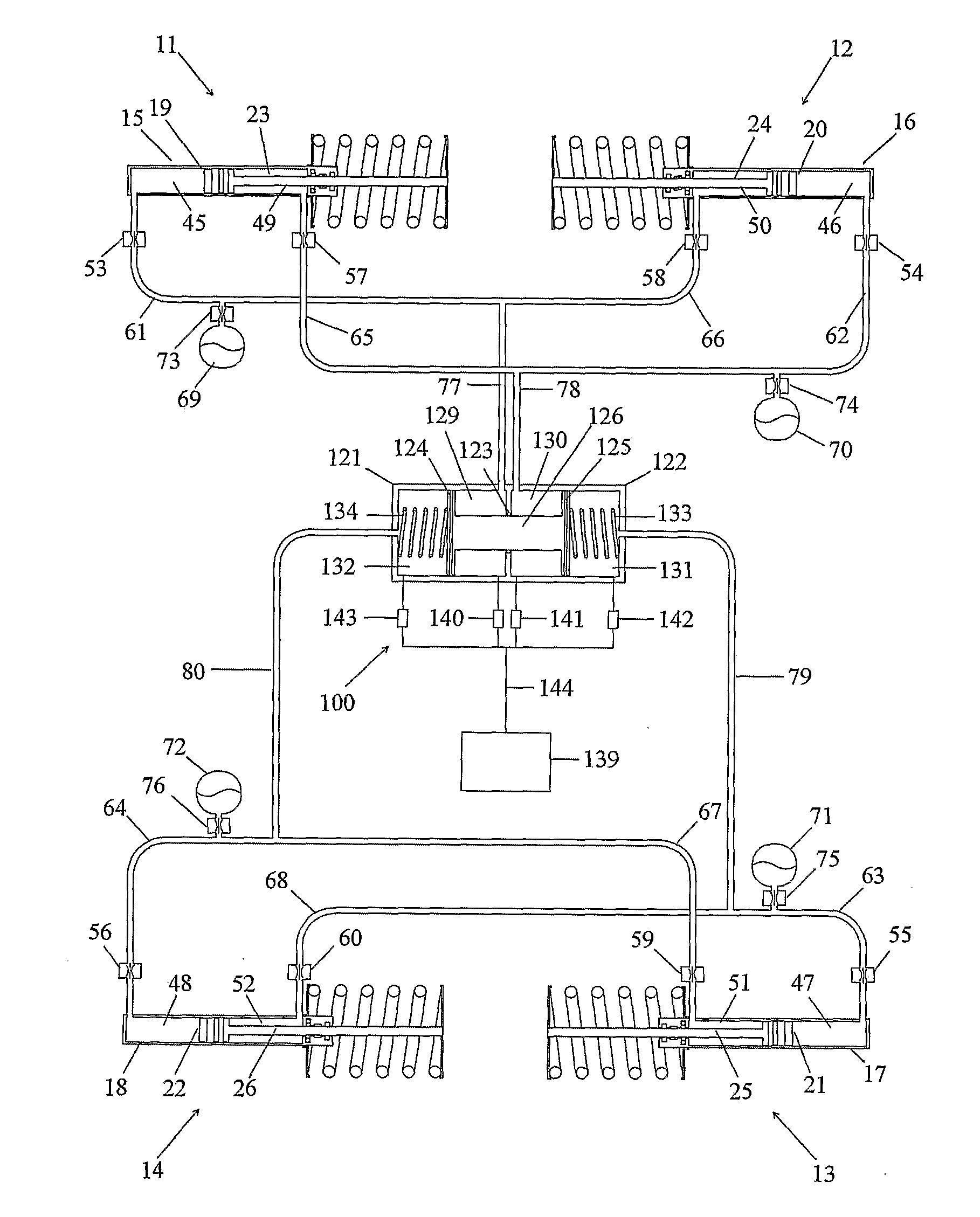
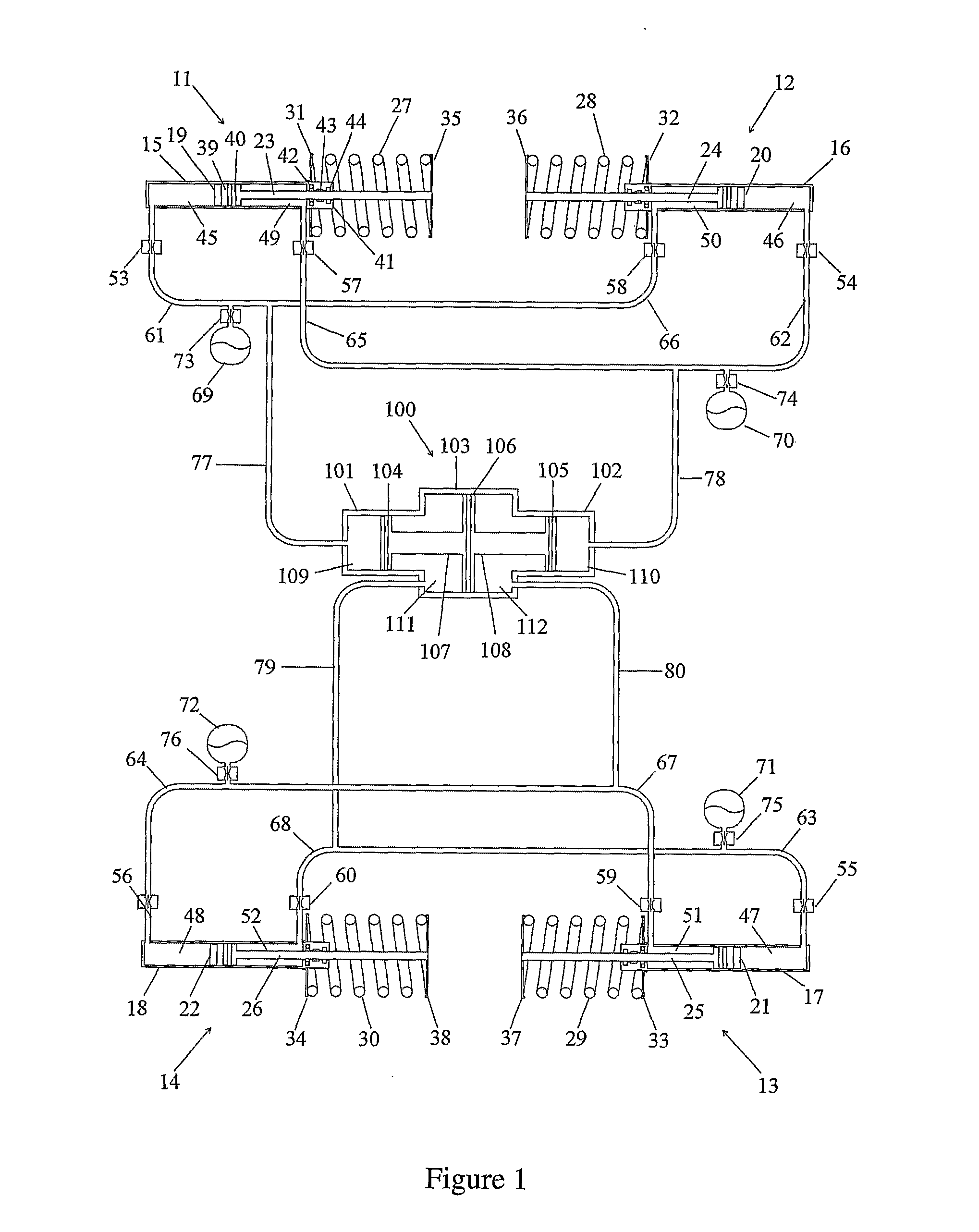
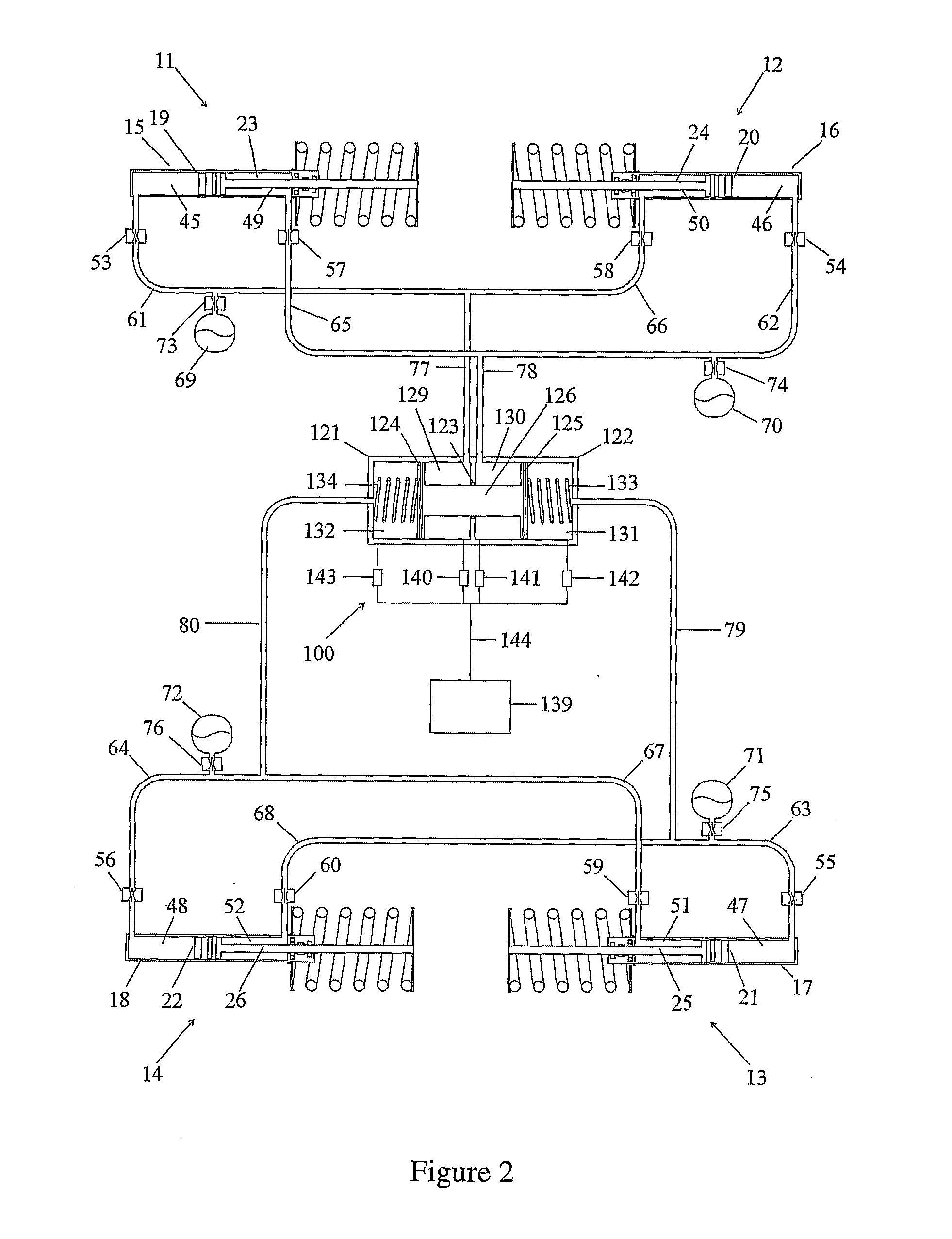
[0044]Referring initially to FIG. 1, there is shown a suspension system for a vehicle. Four wheel rams (11, 12, 13, 14) are located between the vehicle body (not shown) and four orthogonally disposed wheels (not shown) of the vehicle. Each wheel ram includes a cylinder (15, 16, 17, 18) connected to a wheel hub or other suspension geometry to move with the wheel, a piston (19, 20, 21, 22) slidably housed within the cylinder, and a rod (23, 24, 25, 26) fixed between the piston and the body of the vehicle. The connection of the rod to the vehicle body may be by any known means, usually through a rubber bushing which in the case of MacPherson strut geometry usually includes a bearing.

[0045]For ease of understanding, the vehicle resilient support means are shown as “coil-overs”, ie coil springs (27, 28, 29, 30) positioned around the wheel ram and located between a lower spring plate (31, 32, 33, 34) fixed to the cylinder and an upper spring plate (35, 36, 37, 38) which may be connected t...


PUM


Abstract

A vehicle hydraulic suspension system has front left (15), front right (16), rear left (18) and rear right (17) wheel ram. There is a mode decoupling device (100) with first (129), second (130), third (132) and fourth (131) balance chambers formed by a cylinder / piston rod assembly (124,125,126). The compression chamber (45) of the front left wheel ram (15) is in fluid communication with the first balance chamber (129), the compression chamber (46) of the front right wheel ram (16) is in fluid communication with the second balance chamber (130), the compression chamber (48) of the rear left wheel ram (18) is in fluid communication with the third balance chamber (132), and the compression chamber (47) of the rear right wheel ram (17) is in fluid communication with the fourth balance chamber (131). There are also front and rear resilient vehicle support means between vehicle body and the wheel assemblies.

Description

FIELD OF THE INVENTION[0001]The present invention is generally directed to suspension systems for vehicles, and in particular to a hydraulic system providing control of one or more suspension parameters.BACKGROUND OF THE INVENTION[0002]There are known many alternate interconnected suspension systems which have the ability to passively differentiate between different modes of wheel motion with respect to the vehicle body and therefore provide a variety of alternatives in functionality. For example, French patent publication number FR 2 663 267 discloses a hydro-pneumatic suspension system which supports the vehicle body and provides different heave and roll stiffness rates with zero warp stiffness. The pitch stiffness is related to the heave stiffness (which is determined by the rod diameters, accumulator sizes and ram positions front and rear). Since this system supports the vehicle, the pressures in the four fluid volumes must be high, or the rod diameters large to provide the supp...

Claims


Application Information

Patent Timeline
Patent Type & Authority Applications(United States)
IPC IPC(8): B60G21/06B60G17/04
CPCB60G21/06B60G2204/8304B60G2204/80B60G21/00
Inventor MONK, RICHARDTAYLOR, JAMES LIND
Owner KINEHTIK PTI LTD
Why Eureka
Try Eureka