Surface relief diffractive optical elements providing reduced optical losses in electro-active lenses comprising liquid crystalline materials

a liquid crystal lens and diffractive topology technology, applied in the field of surface relief diffractive topological profile within an electroactive ophthalmic lens, can solve the problems of non-conventional errors of the eye, canceling out the optical power provided, and higher order aberrations, so as to improve the alignment of cholesteric liquid crystals and reduce optical scatter. , the effect of reducing optical scatter

Inactive Publication Date: 2008-11-06
PIXELOPTICS
View PDF8 Cites 25 Cited by
  • Summary
  • Abstract
  • Description
  • Claims
  • Application Information

AI Technical Summary

Benefits of technology

[0022]In another embodiment of the present invention, an electro-active lens has a first substrate having a surface relief diffractive topological profile and a second substrate with a substantially smooth topological profile positioned opposite to the first substrate facing the surface relief diffractive topological profile. A first electrode is positioned along the surface relief diffractive topological profile of the first substrate, and a second electrode is positioned between the first electrode and the second substrate. The surface relief diffractive topological profile of the first substrate has sloped side walls and smooth changes in the surface profile, i.e., rounded corners.
[0023]While a surface relief diffractive structure having sloped side walls and smooth changes (rounded corners) in the surface profile may exhibit slightly lower diffraction efficiency than one with nearly vertical side walls and sharp, nearly discontinuous changes in the surface profile, the improved cholesteric liquid crystalline alignment may reduce the optical scatter and improve the overall transmission and cosmetics of the finished lens.
[0024]In certain embodiments of the invention, a mathematical smoothing function may be used to alter the shape of the surface profile for reducing optical scatter. Such functions will be smoothly varying functions and may include linear functions, polynomial functions, trigonometric functions, logarithmic functions, or hyperbolic functions.

Problems solved by technology

Non-conventional errors of the eye include higher order aberrations that can be caused by ocular layer irregularities.
Such matching results in a canceling out of the optical power provided by the diffractive optic to the lens.
One issue with these devices, however, is that they posses mechanisms for optical losses which affect the overall transmission and cosmetics of the finished lens.
However, such geometries do not facilitate well behaved cholesteric liquid crystalline alignment, and disclinations, which are alignment domain boundaries, in the cholesteric liquid crystalline material may result, leading to increased optical scatter.

Method used


Image

  • Surface relief diffractive optical elements providing reduced optical losses in electro-active lenses comprising liquid crystalline materials
  • Surface relief diffractive optical elements providing reduced optical losses in electro-active lenses comprising liquid crystalline materials
  • Surface relief diffractive optical elements providing reduced optical losses in electro-active lenses comprising liquid crystalline materials

Examples


Embodiment Construction

[0041]The following preferred embodiments as exemplified by the drawings are illustrative of the invention and are not intended to limit the invention as encompassed by the claims of this application.

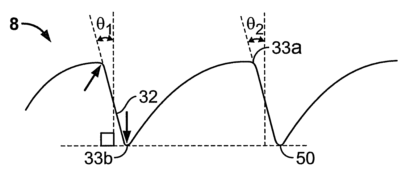
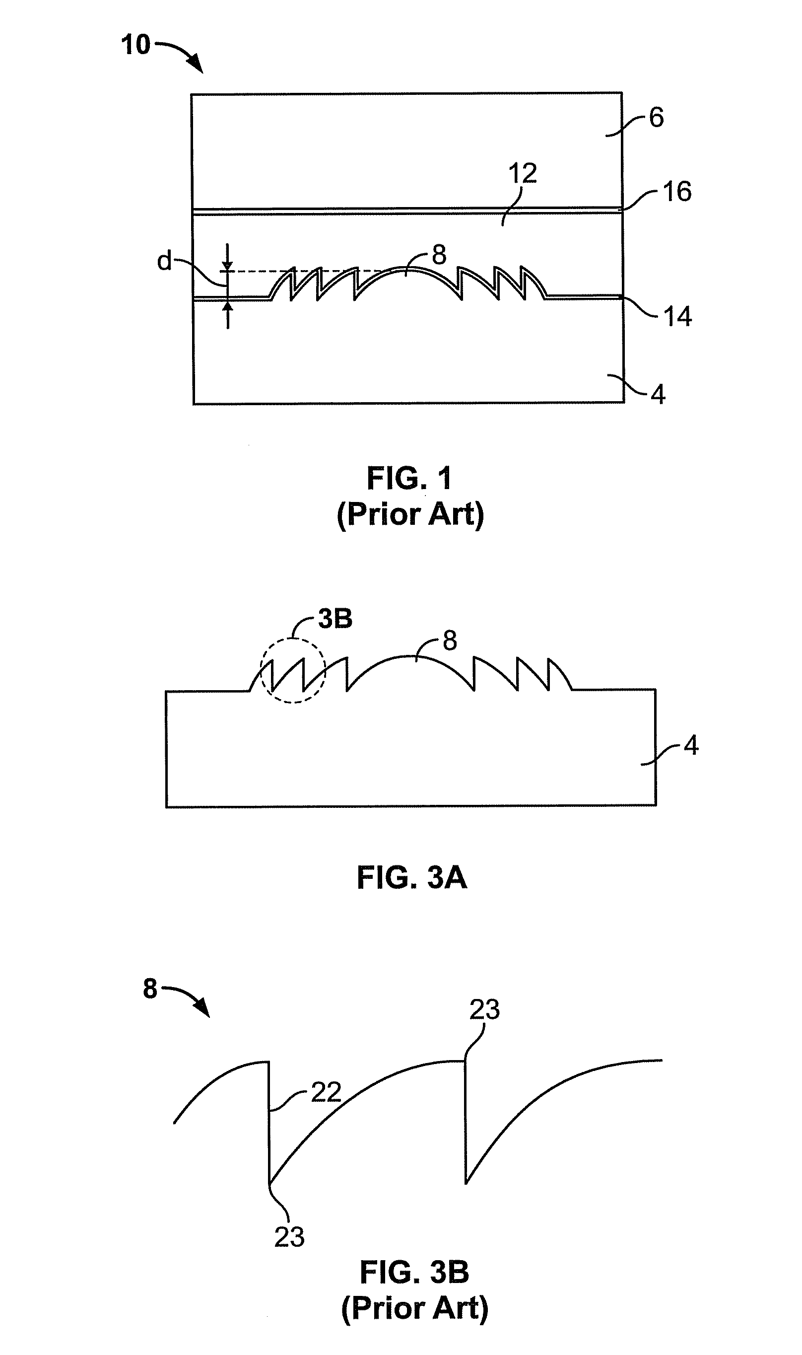
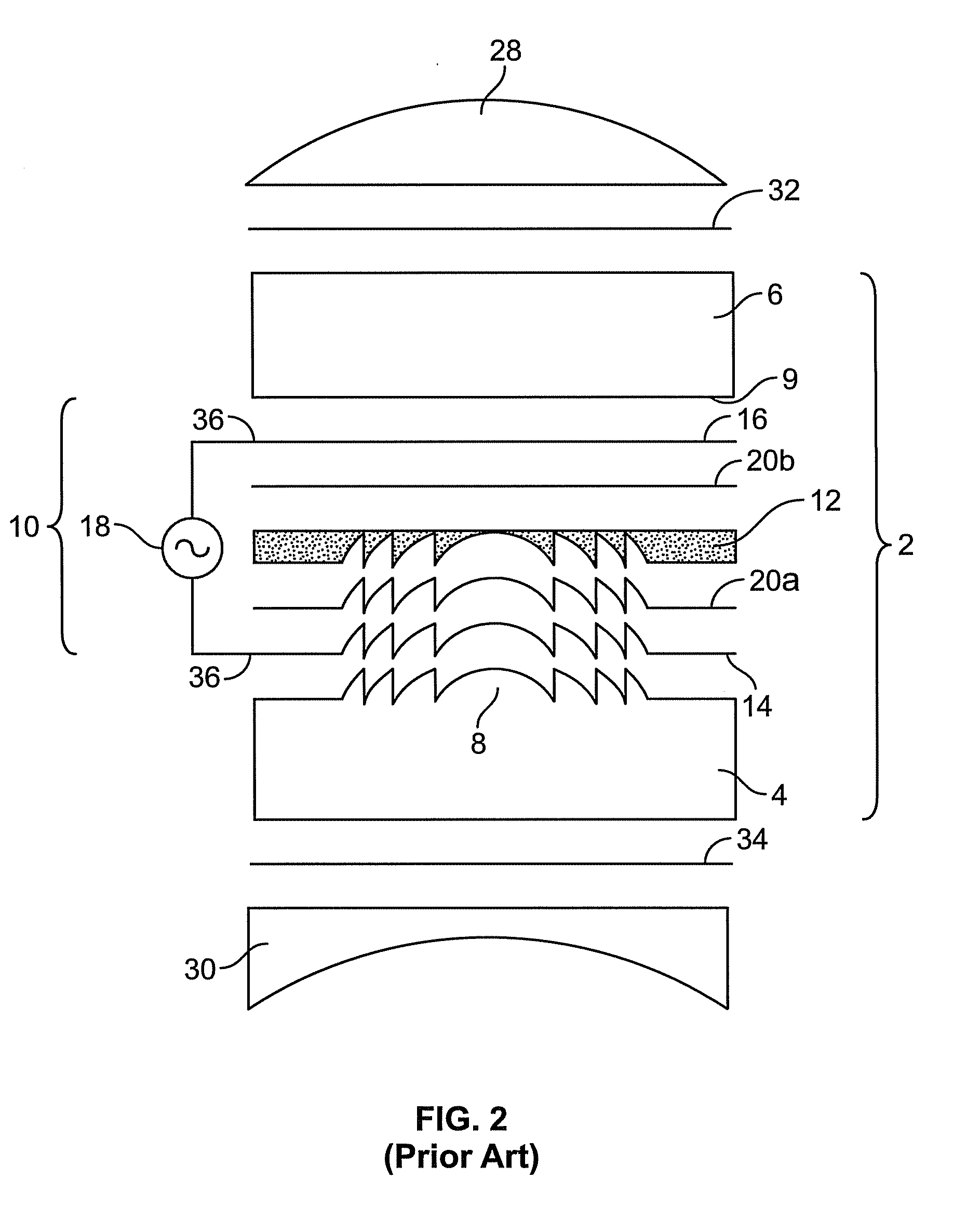
[0042]FIG. 2 shows a schematic exploded cross section of an electro-active lens 2 as known in the art. The electro-active lens may include a first substrate 4 and a second substrate 6 positioned on opposite sides of the lens. The first substrate 4 may have a surface relief diffractive topological profile 8 for diffracting light. As shown in FIG. 3A and more closely in FIG. 3B, the surface relief diffractive profile 8 possesses nearly vertical side walls 22 and inflection points having sharp, nearly discontinuous changes in the surface profile 23, i.e., sharp corners. Having “discontinuous changes” is to be understood herein mathematically as a point at which the first derivative is essentially infinite. In addition, the surface relief diffractive pattern may be considered to have a dept...


PUM


Abstract

An electro-active lens has a first substrate with a surface relief diffractive topological profile and a second substrate positioned opposite to the first substrate having a substantially smooth topological profile. A first electrode is positioned along the surface relief diffractive topological profile of the first substrate, and a second electrode is positioned between the first electrode and second substrates. An electro-active material is positioned between the first and second electrodes. The surface relief diffractive topological profile of the first substrate has been modified to eliminate nearly vertical side walls and/or sharp, nearly discontinuous changes in the surface profile, to instead be characterized by sloped side walls and smooth changes in the surface profile, i.e., rounded corners. The radius of curvature of the rounded corners may be, by way of example only, between 1 μm and 100 μm, the slope of the side walls may be at some angle θ, or the shape of the surface profile may be determined by a mathematical smoothing function.

Description

CROSS REFERENCE TO RELATED APPLICATIONS[0001]This application claims priority under 35 U.S.C. §119(e) from, and incorporates by reference in its entirety, U.S. Provisional Application No. 60 / 924,116, filed on May 1, 2007 and entitled “Methods for Reducing Optical Losses in Electro-Active Lenses Comprising Liquid Crystalline Materials and Surface Relief Diffractive Optical Elements”.BACKGROUND OF THE INVENTION[0002]1. Field of the Invention[0003]The present invention relates to the use of a surface relief diffractive topological profile within an electro-active ophthalmic lens. More specifically, the present invention relates to modifications to surface relief diffractive topological profiles within an electro-active element or electro-active lens to prevent scattering of light in the cholesteric liquid crystal within the electro-active element.[0004]2. Description of the Related Art[0005]Electro-active lenses may be used to correct for conventional or non-conventional errors of the ...

Claims


Application Information

Patent Timeline
Patent Type & Authority Applications(United States)
IPC IPC(8): G02C7/02G02B27/42
CPCG02B5/1866G02B5/1876G02B5/188G02B26/004
Inventor CLARKE, ROGER
Owner PIXELOPTICS
Why Eureka
Try Eureka