Network system, information processor, and information processing program recording medium

a applied in the field of network system and information processing technology, can solve the problems of reducing affecting the stability of content distribution, and reducing the processing load of topology controllers. , to achieve the effect of improving content distribution stability, reducing the processing load of topology controllers, and good balan

Inactive Publication Date: 2008-11-06
BROTHER KOGYO KK
View PDF9 Cites 24 Cited by
  • Summary
  • Abstract
  • Description
  • Claims
  • Application Information

AI Technical Summary

Benefits of technology

[0012]The present invention has been achieved in view of the problems and demands. The goal of present invention is to provide a network system, a node included in the network system, and a recording medium where a control program for controlling the operation in the node is recorded, capable of realizing, in good balance, both reduction in the processing load on a topology controller and improvement in stability in distribution of content of the network system.

Problems solved by technology

However, the technique of JP-A No. 2006-287351 has a problem such that, since a single topology controller controls the topologies of all of the nodes, when the number of nodes becomes enormous in the network system, the topology controller becomes overloaded.
In this case, when the topology controller becomes overloaded, for example, even when a new node transmits request information to join the network system, the reply including information of a corresponding connection destination from the topology controller is delayed, or useless time is required to reconstruct a topology when a node leaves the network system.
At worst, a problem occurs such that when anode leaves the upstream side, distribution of content to downstream side has the potential of disruption.

Method used


Image

  • Network system, information processor, and information processing program recording medium
  • Network system, information processor, and information processing program recording medium
  • Network system, information processor, and information processing program recording medium

Examples


first embodiment

(I) First Embodiment

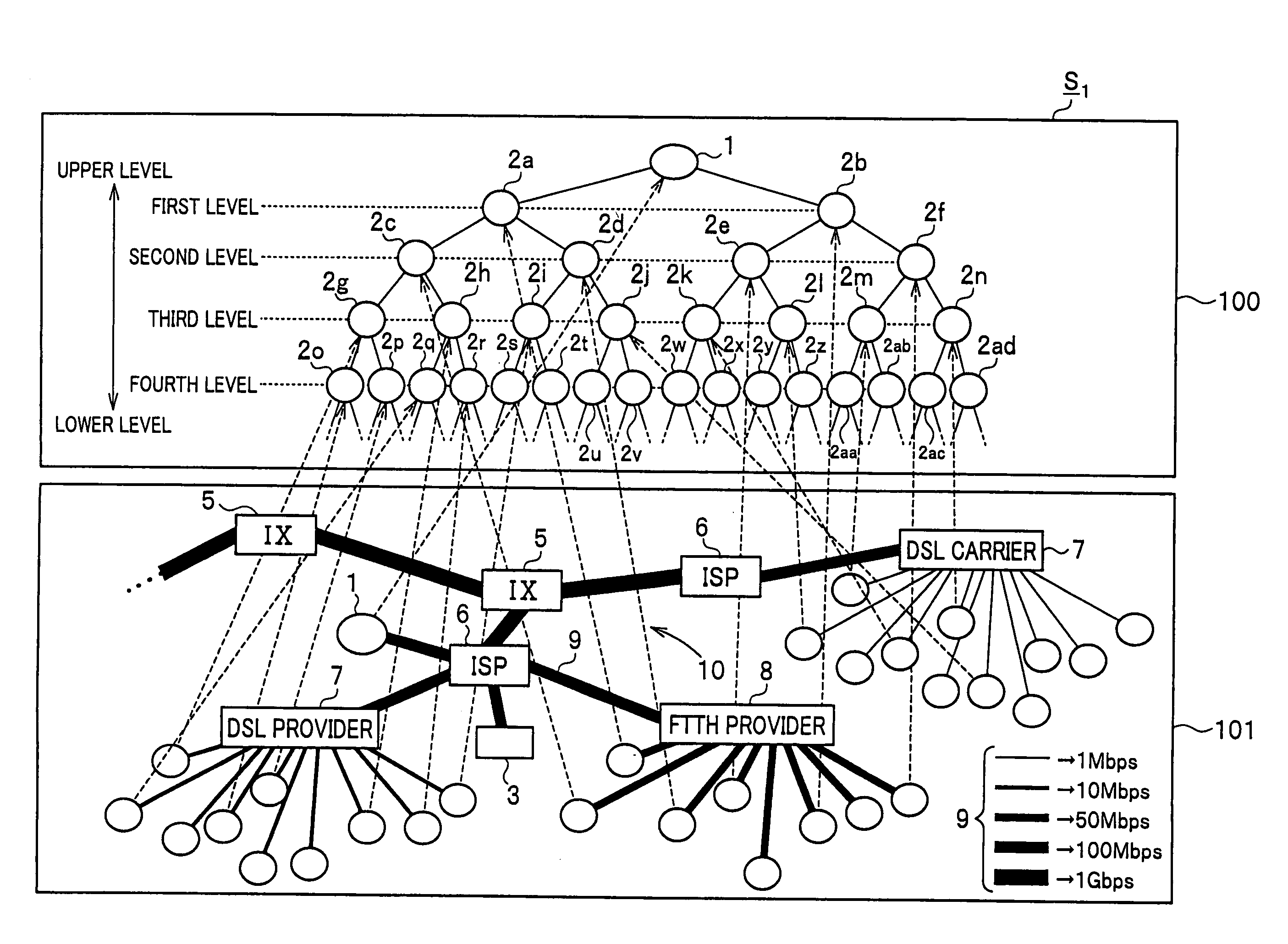
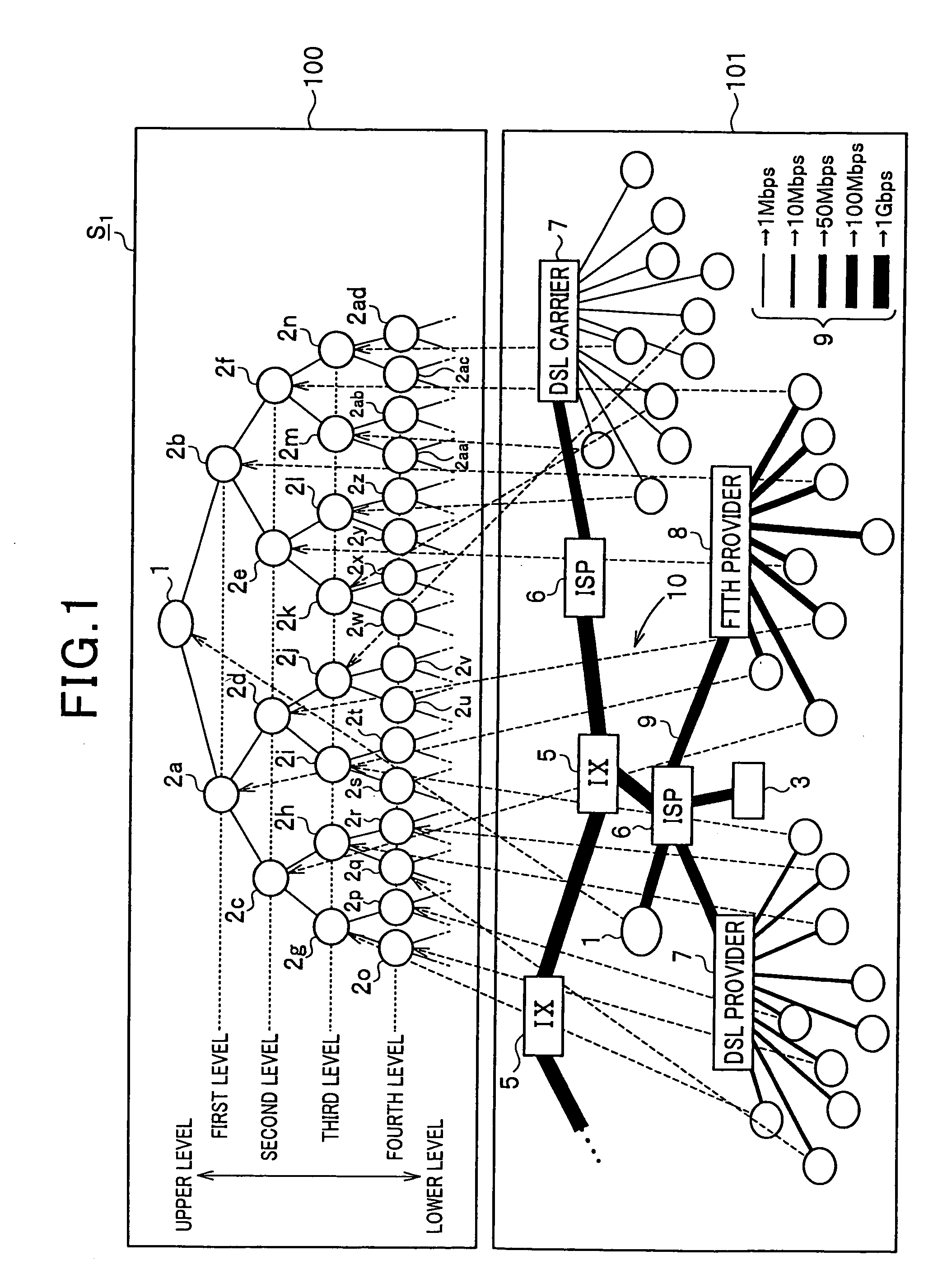
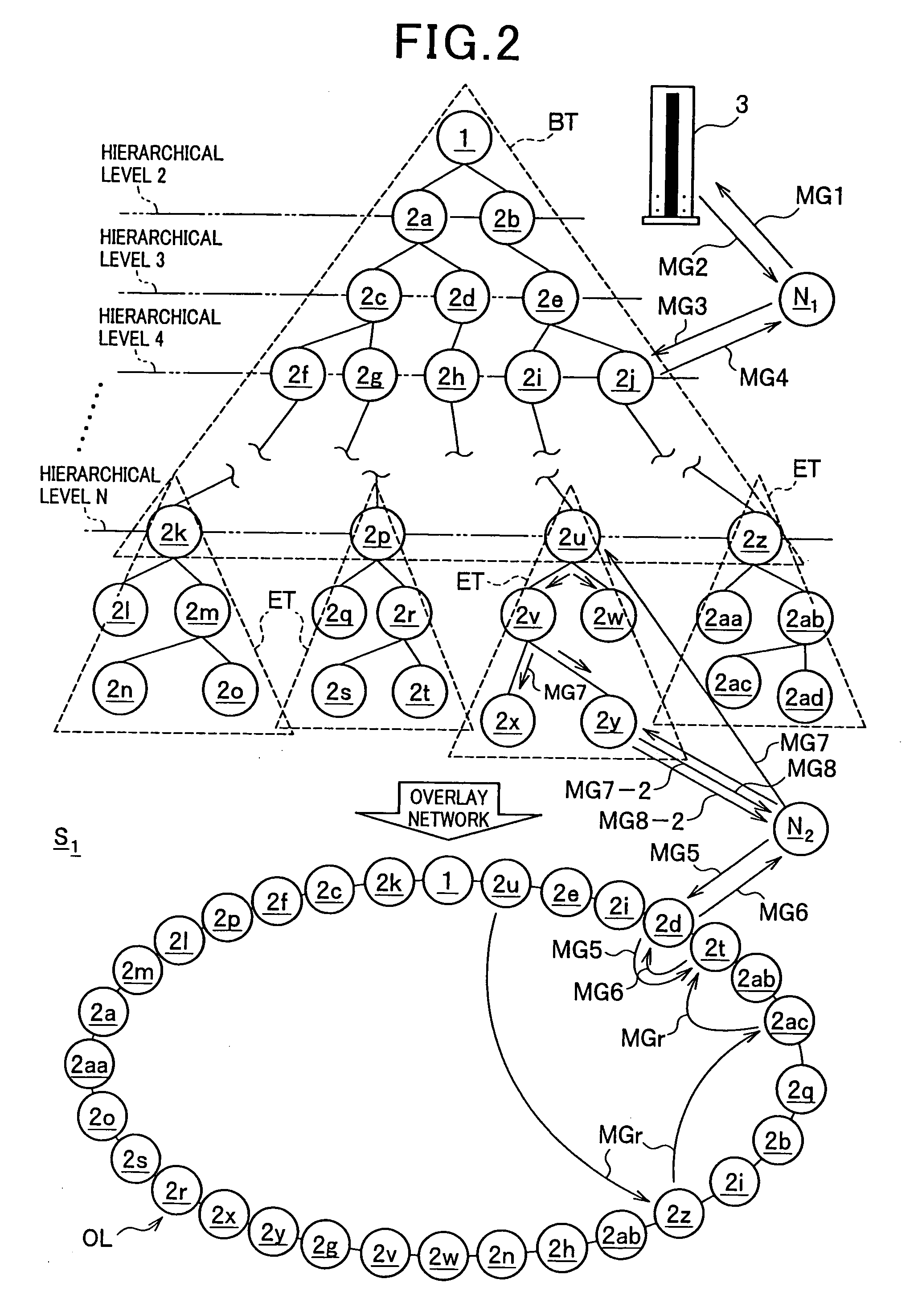
[0037]A first embodiment according to the present invention will be described with reference to FIGS. 1 to 4. FIGS. 1 and 2 are diagrams showing an example of a logical network connection aspect of nodes constructing a distribution system of the first embodiment. FIGS. 3 and 4 are diagrams showing processes in the case where a node leaves the distribution system.

(A) General Configuration of Distribution System

[0038]First, a schematic configuration and function of the distribution system of the first embodiment will be described with reference to FIG. 1.

[0039]As shown in FIG. 1, a distribution system S1 of the first embodiment is constructed by using a network (network in the real world) such as the Internet. Concretely, for example, as shown in a lower frame 101 in FIG. 1, a network 10 of the real world includes IXs (Internet exchanges) 5, ISPs (Internet Service Providers) 6, DSL (Digital Subscriber Line) providers (apparatuses) 7, FTTH (Fiber To The Home) provid...

second embodiment

(II) Second Embodiment

[0076]A second embodiment according to the present invention will now be described with reference to FIG. 5. FIG. 5 is a diagram showing an example of the logical network connection aspect of nodes constructing a distribution system of the second embodiment. The same reference numerals are designated to components similar to those of the distribution system S1 in the first embodiment shown in FIG. 2, and description of the details of the similar components will be omitted.

[0077]In the distribution system S1 of the first embodiment, the number of levels in the base tree BT to which the first root nodes at the apexes of the extension trees ET belong is constant (N in the example of FIG. 2) in all of the extension trees ET. The number of levels is preset on the basis of the throughput or the like of the topology controller 3.

[0078]On the other hand, in the distribution system of the second embodiment described below, the number of levels in the base tree BT in whi...

third embodiment

(III) Third Embodiment

[0082]A third embodiment according to the present invention will now be described with reference to FIG. 6. FIG. 6 is a diagram showing an example of the logical network connection aspect of nodes constructing a distribution system of the third embodiment. The same reference numerals are designated to components similar to those of the distribution system S1 in the first embodiment shown in FIG. 2, and description of the details of the similar components will be omitted.

[0083]In the distribution systems S1 and S2 of the first and second embodiments, a level in the base tree BT to which the first root node as the apex of the extension tree ET is to belong is pre-set by the topology controller 3 on the basis of the throughput of the topology controller 3 itself.

[0084]In contrast, in the distribution system of the third embodiment described below, the node 2 serving as the first root node at the apex of the extension tree is selected in consideration of not only t...


PUM


Abstract

A content distribution system in which content is distributed from a broadcasting station via a plurality of nodes connected in a hierarchical tree structure, including: a base tree obtained by connecting the plurality of nodes in a hierarchical tree structure using the broadcasting station as an apex; an extension tree obtained by connecting the plurality of other nodes in a hierarchical tree structure using, as an apex, a first root node as any of the nodes included in the base tree; and a topology controller for controlling a topology of each of the nodes belonging to the base tree.The first root node controls the topology of each of the nodes belonging to the extension tree using the first root node as an apex.

Description

CROSS REFERENCE TO RELATED APPLICATIONS[0001]The present application claims priority from Japanese Patent Application NO. 2007-090770, which was filed on Mar. 30, 2007, the disclosure of which is herein incorporated by reference in its entirety.BACKGROUND OF THE INVENTION[0002]1. Field of the Invention[0003]The present invention belongs to the technical fields of a network system, an information processor, and a recording medium storing information programs. More specifically, the invention belongs to the technical fields of a distributed network system in which a distributor delivers information to information processors that connects each other in a hierarchical fashion for relaying the information from end to end stepwisely.[0004]2. Description of Related Art[0005]In recent years, as the speed of the Internet line for home use increases, a network system is being widespread. In the network system, a network is constructed by connecting a plurality of personal computers or the lik...

Claims


Application Information

Patent Timeline
Patent Type & Authority Applications(United States)
IPC IPC(8): H04L12/28G06F13/00H04L12/44H04N7/173H04N21/61
CPCH04L45/04H04L45/48H04L45/488
Inventor YANAGIHARA, YASUSHI
Owner BROTHER KOGYO KK
Why Eureka
Try Eureka