

Turbine nozzle segment and repair method
- Summary
- Abstract
- Description
- Claims
- Application Information
AI Technical Summary
Benefits of technology
Problems solved by technology
Method used
Image

Examples
Embodiment Construction
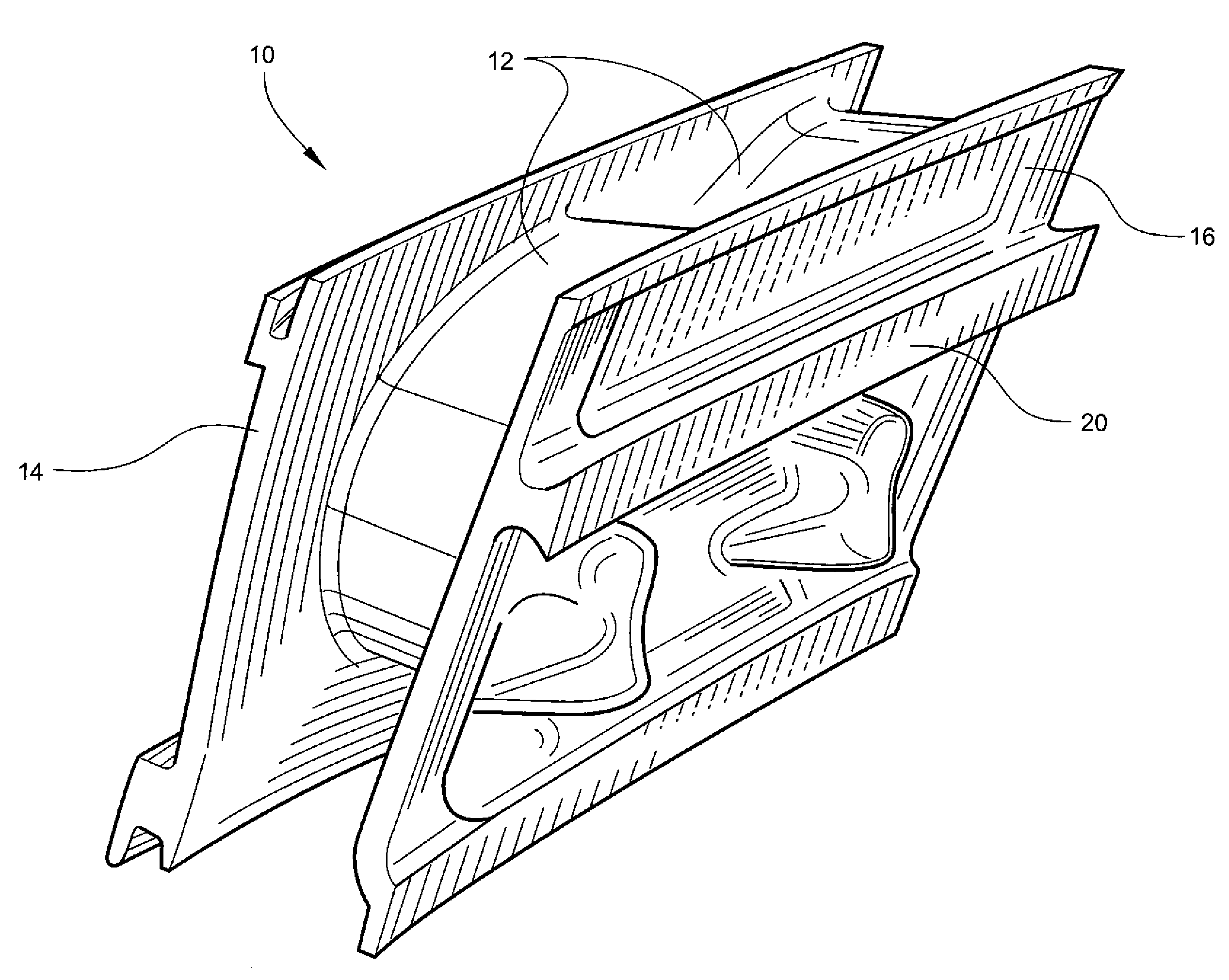
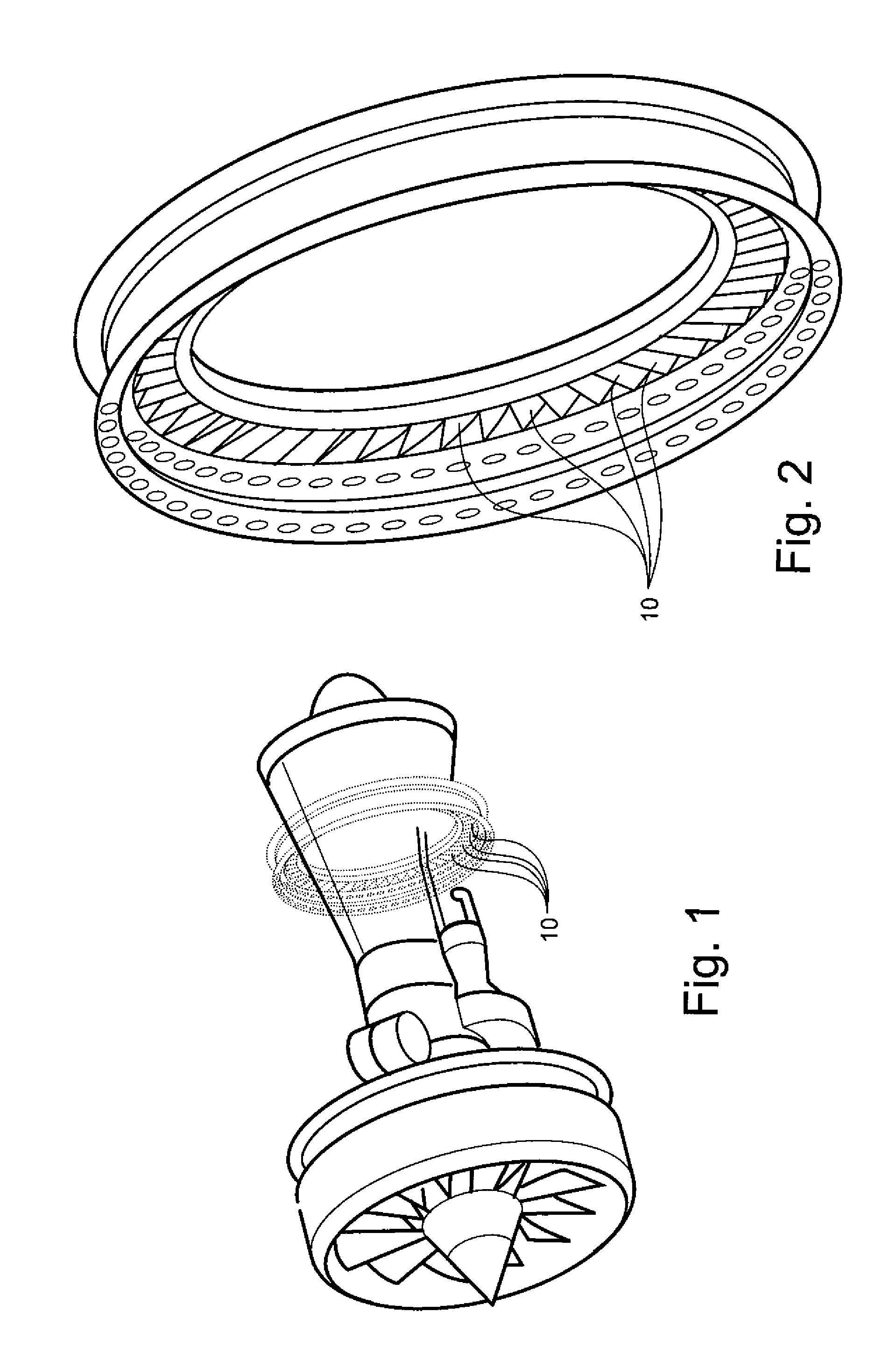
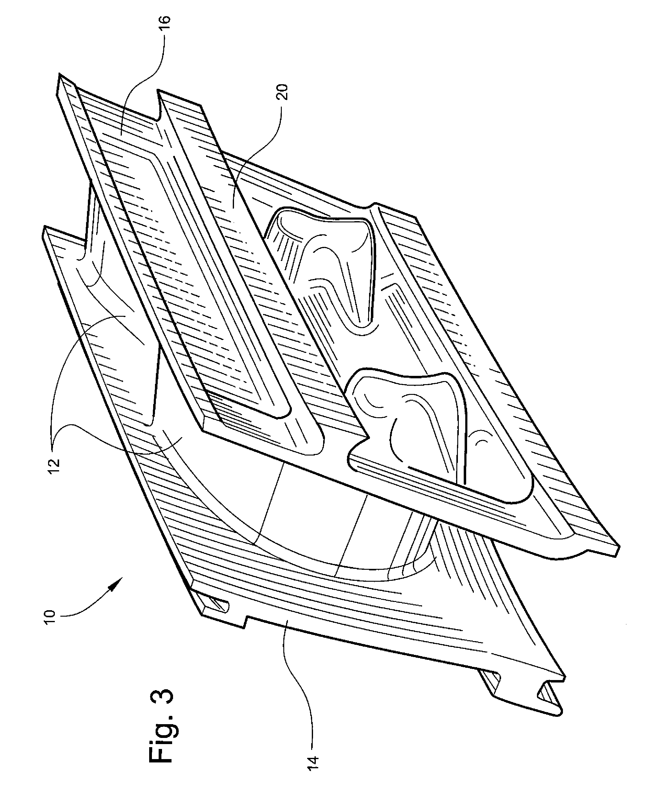
[0019]Referring to the drawings wherein identical reference numerals denote the same elements throughout the various views, FIG. 1 is a perspective view of a high bypass turbine engine of the type having an annular array of stage 2 HPT nozzle segments 10, as described below. The gas turbine engine, such as shown by way of example in FIG. 1, includes a plurality of nozzle segments 10 arranged circumferentially in an annular configuration, also as shown in FIG. 2. While the repair method of the present invention is described herein with respect to a two-vane nozzle segment of a stage 2 HPT nozzle, the repair method described in this application is equally applicable to nozzle segments having any number of vanes and utilized in other engine locations.
[0020]During engine operation, a nozzle segment can experience damage from, for example, local gas stream over-temperature or foreign object impacts. As mentioned above, a portion of the nozzle segment 10 may become damaged to the point wh...
PUM
 Abstract
Description
Claims
Application Information