Vehicle active suspension system

a suspension system and active technology, applied in repeater circuits, cycle equipment, instruments, etc., can solve the problems of engine damage, high cost, and inability to detect nois

Active Publication Date: 2008-11-06
DEERE & CO
View PDF3 Cites 41 Cited by
  • Summary
  • Abstract
  • Description
  • Claims
  • Application Information

AI Technical Summary

Benefits of technology

[0004]Accordingly, an object of this invention is to provide an active suspension system which can be used to alert an operator about the existence of a critical or non-optimal operating state of the vehicle.
[0010]Preferably, the movement produced by the actuator has a predetermined frequency which is not in a natural frequency range of the vehicle or of the operator. Accordingly, the active movement should not lead to a build-up of the suspension system and thus to a dangerous situation of the utility vehicle and / or the components thereof. For active movements of longer duration, the active movement frequency should not be near the natural frequency range of the operator, for example a frequency of the range of 2 Hz to 7 Hz, which is the natural frequency of the human stomach, so that the operator does not feel unwell.

Problems solved by technology

If the engine is continuously operated above the normal maximum operating speed, a conventional utility vehicle will have no further indicators, apart from increased noise generated by the engine.
This noise may not be detected if the cab of the utility vehicle is well sound-proofed.
This may lead to engine damage and thus to inconvenience and high costs.
Above all, this could be relevant for trailers (for example a sprayer with an extended spraying boom) attached to the utility vehicle, which for example carry out rolling and / or yaw movements due to the unevenness of the ground and thus may bring the utility vehicle and the trailer into a dangerous overall state.

Method used


Image

  • Vehicle active suspension system
  • Vehicle active suspension system
  • Vehicle active suspension system

Examples


second embodiment

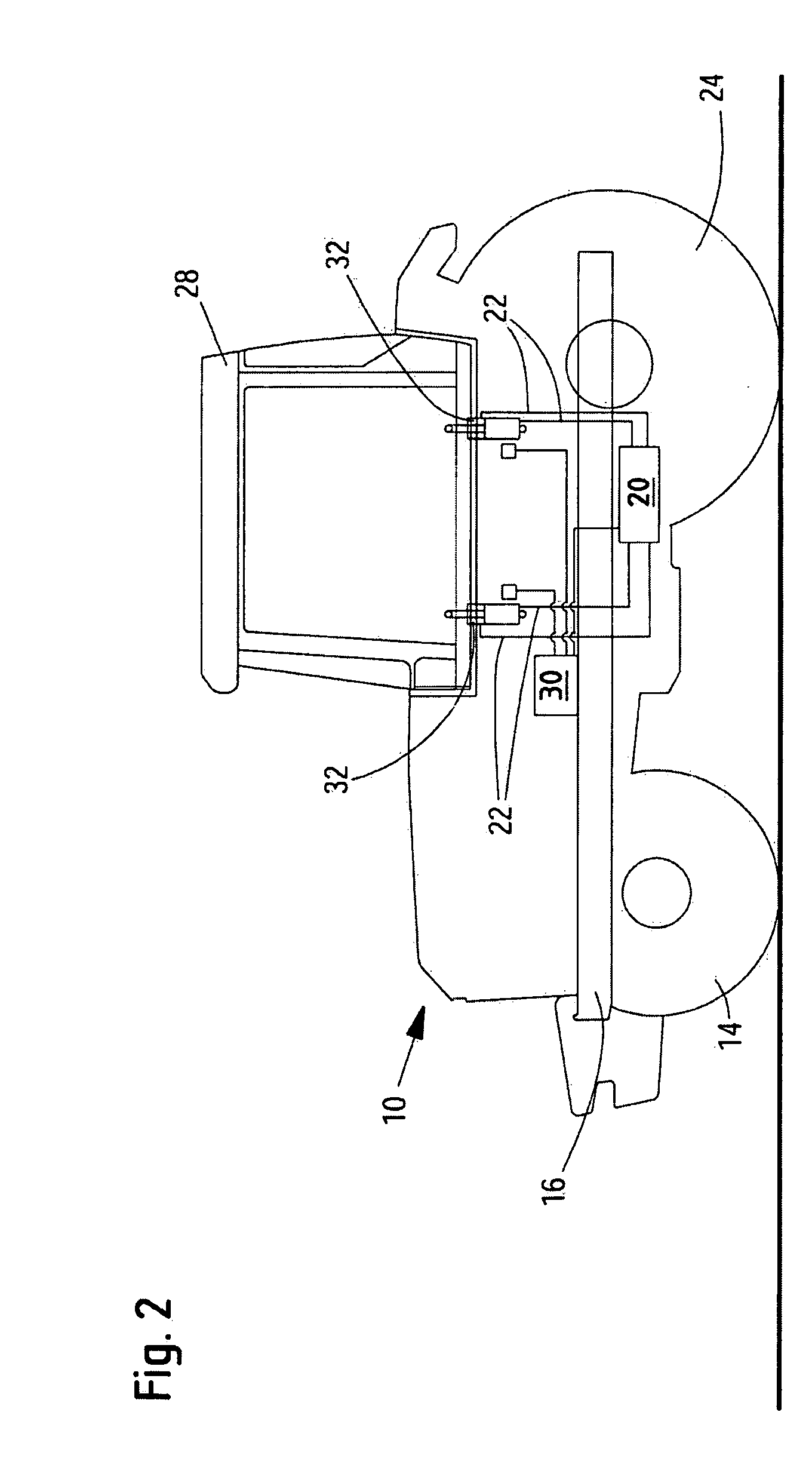
[0031]FIG. 2 shows an active suspension system in which the cab 28 (the second part) is supported relative to the vehicle frame 16 (the first part) by the actuators 32 in a resilient and dampened manner. Also in this case, the suspension and / or damping is active. The hydraulic system 20 includes accumulators and throttles (not shown) dimensioned accordingly for the damping. This embodiment includes four actuators 32, namely two actuators 32 on the left-hand side and two actuators 32 on the right-hand side. An embodiment of the active suspension system with only two actuators 32 might be also conceivable, for example merely one actuator arranged to the rear on the left-hand side and one actuator arranged to the rear on the right-hand side.

third embodiment

[0032]FIG. 3 shows an active suspension system in which the vehicle seat 34 (the second part) is supported relative to the cab 28 (the first part). To this end, two actuators 36 are provided, by means of which the vehicle seat 34 is mounted relative to the cab 28 in a resilient and / or dampened manner.

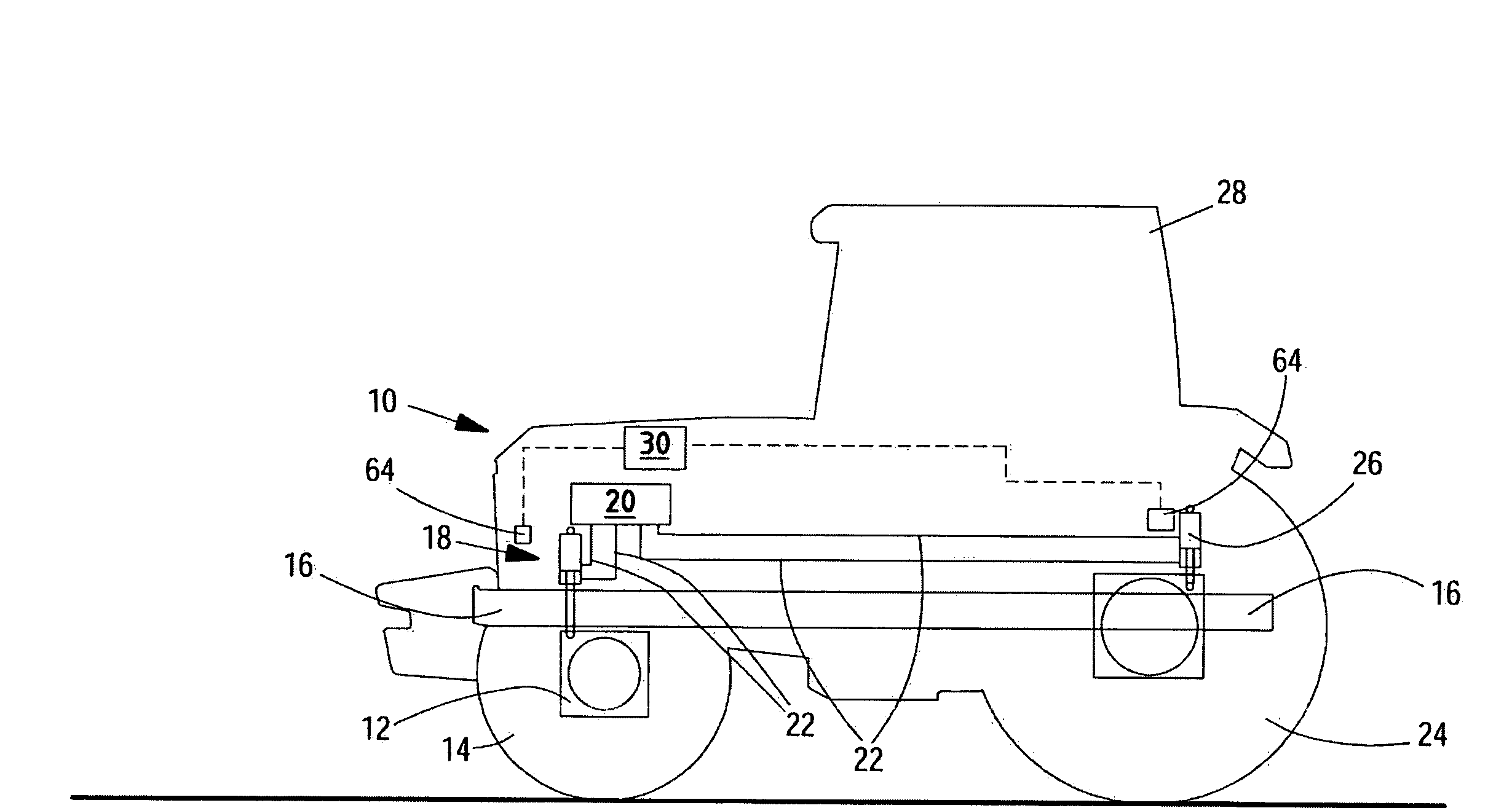
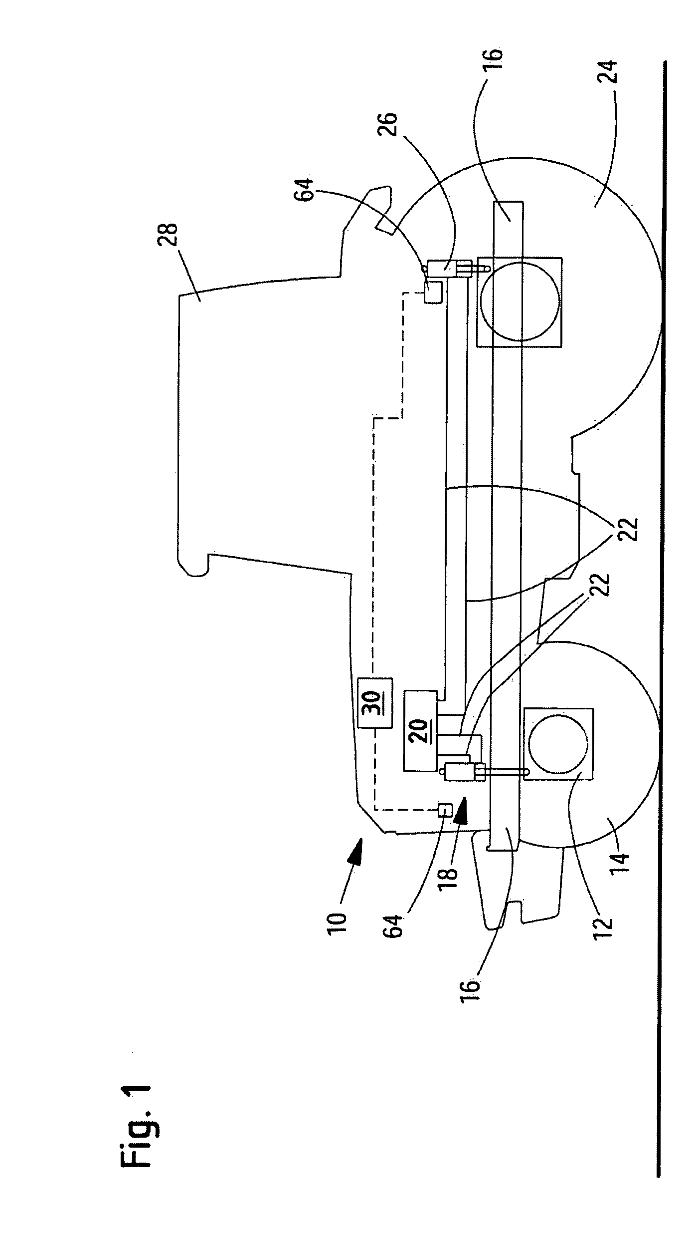
[0033]FIGS. 1 to 3 show respective suspension systems, where a second part is movable relative to a first part. Although not shown, a utility vehicle could include both a cab suspension system according to FIG. 2 and a seat suspension system according to FIG. 3. In this case, the actuators could be controlled to provide operator comfort, and the actuators could be actively controlled to inform an operator of the existence of a non-optimal or an unsafe operating condition. In this case, the systems are mutually dependent which is to be taken into account during the control.

[0034]The actuators 18, 26, 32, 36 may be controlled to carry out a predetermined movement, such as a periodic movem...


PUM


Abstract

The invention relates to a vehicle active suspension system. There is a need for an active suspension system which can alert an operator to certain conditions. The suspension system includes an actuator for moving a second vehicle part relative to a first vehicle part. The suspension system also includes sensors and a control unit. A vehicle operator is located in or on the second part. The sensors sense vehicle parameters and transmit parameter signals to the control unit. In response to the parameter sensors, the control unit causes the actuator to move the second part in such a manner that the movement alerts the operator to the existence of a condition, such as a critical or non-optimal operating state of the utility vehicle or of an implement coupled to the vehicle.

Description

FIELD OF THE INVENTION[0001]The present invention relates to an active suspension system for an agricultural or industrial utility vehicle.BACKGROUND OF THE INVENTION[0002]Active suspension systems are used on utility vehicles, such as tractors, harvesting machines, combine harvesters, forage harvesters, self-propelled sprayers, as well as industrial utility vehicles, such as construction vehicles, bulldozers, graders, backhoe excavators, loader vehicles, tipper trucks, cranes and telescopic loaders. Active suspension systems are suspension and damping systems, by means of which movements between a first part and a second part of the vehicle are cushioned and / or dampened. Such systems are known from the prior art, in particular with a seat suspension system of the applicant, which is disclosed in EP 1 186 467 B1. Such active suspension systems are also used in chassis of vehicles—generally large executive cars. A known axle suspension system is described in EP 0 913 280 A1. Such sys...

Claims


Application Information

Patent Timeline
Patent Type & Authority Applications(United States)
IPC IPC(8): G06F19/00
CPCB60G17/016B60G99/008B60G2206/911B60G2300/08B60G2600/044B60N2/0244B60N2/39
Inventor TARASINSKI, NICOLAIHAHN, KLAUS
Owner DEERE & CO
Why Eureka
Try Eureka