Method and apparatus to determine rotational position of an internal combustion engine

a technology of internal combustion engine and rotational position, which is applied in the direction of gearing, dynamo-electric converter control, instruments, etc., can solve the problems of difficult control of the installation of the resolver and the mechanical alignment, the subject of error in the position of the resolver relative to the machine rotor, and the direct influence of the accuracy of measuremen

Active Publication Date: 2008-11-06
GM GLOBAL TECH OPERATIONS LLC
View PDF2 Cites 157 Cited by
  • Summary
  • Abstract
  • Description
  • Claims
  • Application Information

AI Technical Summary

Benefits of technology

[0007]It is therefore an object of this invention to provide a control system for a hybrid powertrain which determines engine crank angle position based upon signal inputs from electric machines of the powertrain. The hybrid powertrain comprises an internal combustion engine and electric machines and an electromechanical transmission selectively operative to transmit torque therebetween. The electric machines are rotatably fixedly coupled to the internal combustion engine via a transmission input shaft and a gear set. Control modules are adapted to execute a control scheme to determine engine crank angle position. The control scheme comprises code to determine an input shaft angle based upon rotational positions of the electric machines. An offset angle of the input shaft and an angular twist between the engine and the transmission are determined. An engine crank angle offset is determined based upon the offset angle and the angular twist of the input shaft.

Problems solved by technology

Position of the resolver relative to the machine rotor is subject to error due to factors including manufacturing variations and tolerances.
Also, the accuracy of this position measurement is critical, as it can affect the performance of the motor control, most noticeably in torque production and linearity.
However, the accuracy of the measurement is directly affected by the initial alignment of the resolver during installation.
The installation of the resolver and mechanical alignment can be difficult to control in production, and is typically addressed by employing a self-aligning start-up algorithm in the motor control.
Furthermore, alignment of the resolver relative to the crankshaft of the attached internal combustion engine can be affected by initial installation of various components and by twisting occurring during operation.

Method used


Image

  • Method and apparatus to determine rotational position of an internal combustion engine
  • Method and apparatus to determine rotational position of an internal combustion engine
  • Method and apparatus to determine rotational position of an internal combustion engine

Examples


Embodiment Construction

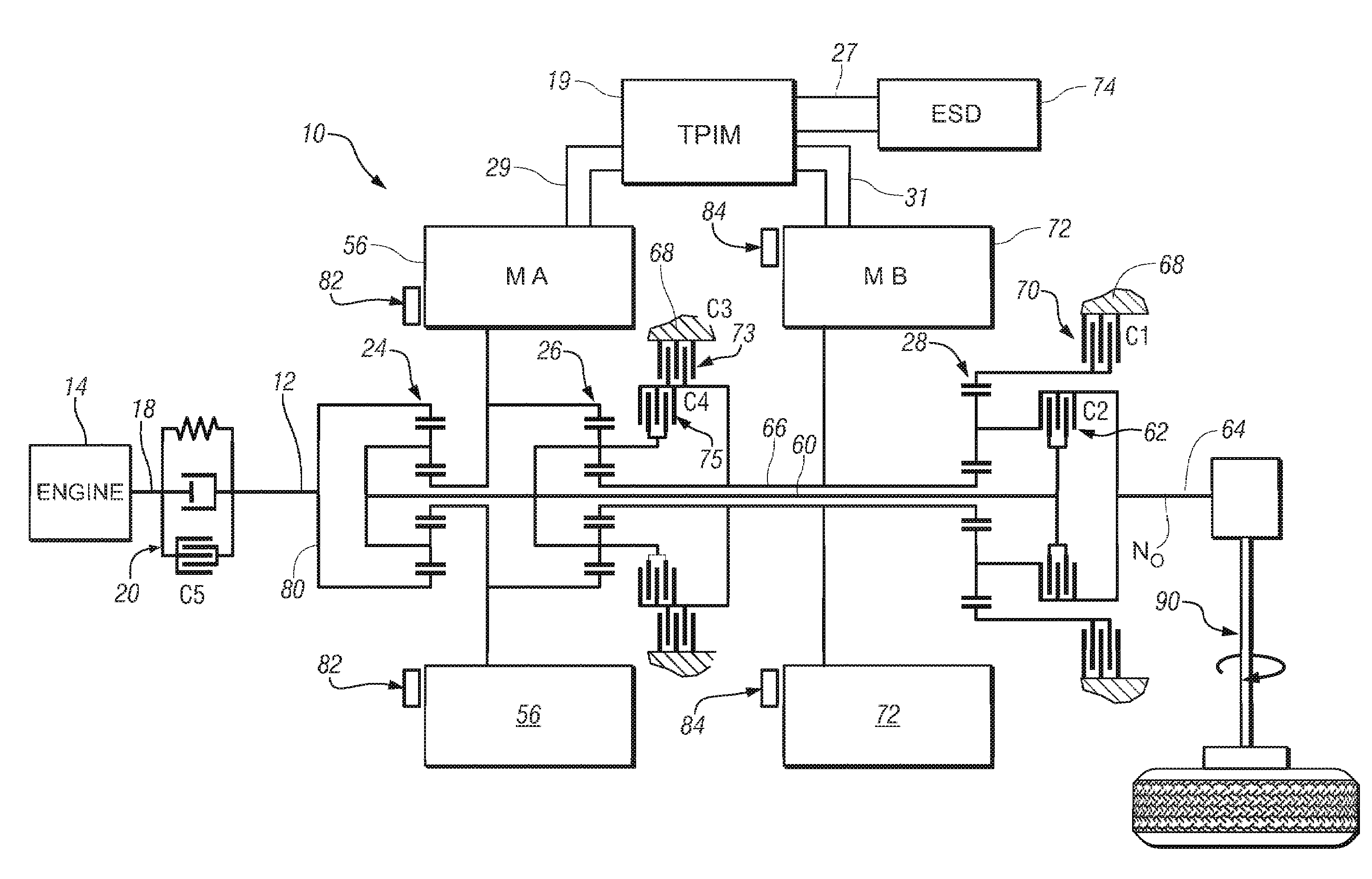
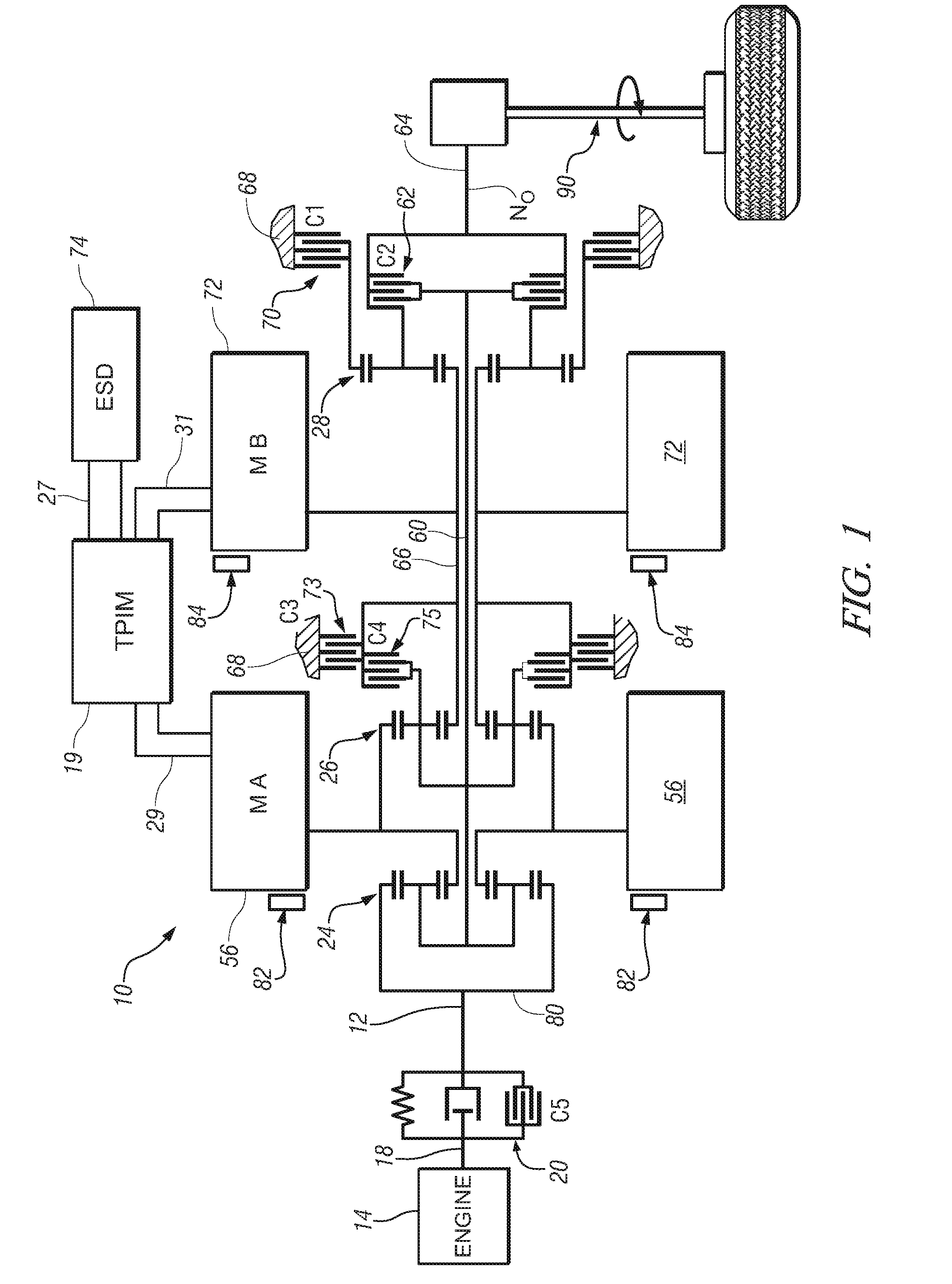
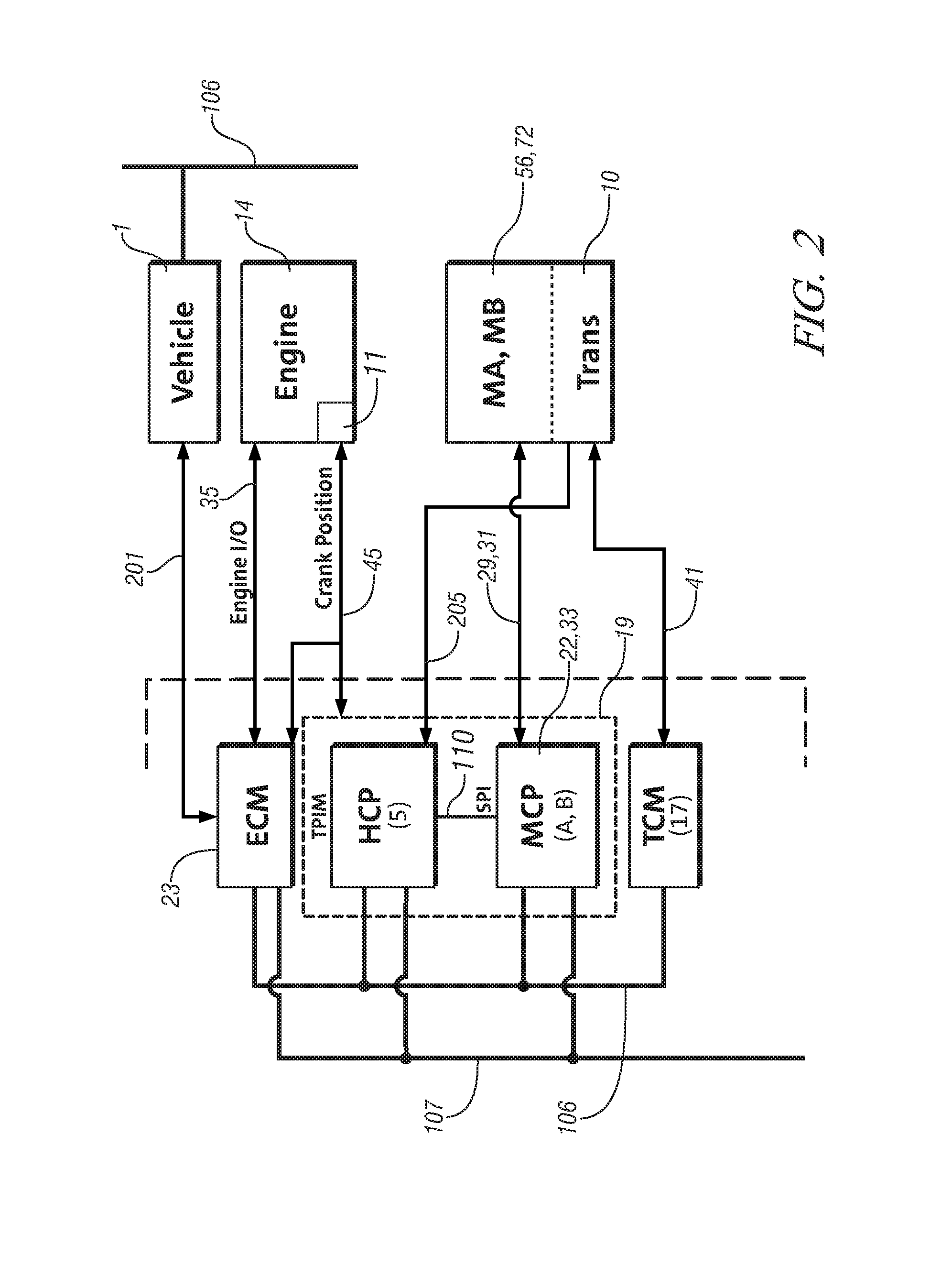
[0012]Referring now to the drawings, wherein the showings are for the purpose of illustrating the invention only and not for the purpose of limiting the same, FIGS. 1, 2, and 3 depict a schematic diagram of a hybrid powertrain system comprising an engine 14, an electromechanical transmission 10, control system, and driveline which has been constructed in accordance with an embodiment of the present invention. Mechanical aspects of exemplary transmission 10 are disclosed in detail in commonly assigned U.S. Pat. No. b 6,953,409, entitled “Two-Mode, Compound-Split, Hybrid Electro-Mechanical Transmission having Four Fixed Ratios”, which is incorporated herein by reference. The exemplary two-mode, compound-split, electromechanical hybrid transmission embodying the concepts of the present invention is depicted in FIG. 1, and is designated generally by the numeral 10. The transmission 10 includes an input shaft 12 characterized by an input rotational speed, N1 and rotation angle θ1, and is...


PUM


Abstract

A control system for a hybrid powertrain which determines engine crank angle position based upon signal inputs from electric machines of the powertrain is provided. The hybrid powertrain comprises an internal combustion engine and electric machines and an electromechanical transmission selectively operative to transmit torque therebetween. The electric machines are rotatably fixedly coupled to the internal combustion engine via a transmission input shaft. Control modules are adapted to execute a control scheme to determine engine crank angle position. The control scheme comprises code to determine an input shaft angle based upon rotational positions of the electric machines. An offset angle of the input shaft and an angular twist between the engine and the transmission are determined. An engine crank angle offset is determined based upon the offset angle and the angular twist of the input shaft.

Description

TECHNICAL FIELD[0001]This invention pertains generally to control of a hybrid powertrain system, and more specifically to a control system to determine a rotational position of an internal combustion engine therefor.BACKGROUND OF THE INVENTION[0002]Vehicle propulsion systems comprising hybrid powertrains are known for managing the input and output torques of various torque-generative devices, most commonly internal combustion engines and electric machines. One hybrid powertrain architecture comprises a two-mode, compound-split, electromechanical transmission which utilizes an input member for receiving torque from a torque-generative source, e.g. an internal combustion engine, and an output member for delivering motive torque from the transmission to a vehicle driveline. The internal combustion engine and first and second electric machines and the electromechanical transmission are selectively operative to transmit torque therebetween. The first and second electric machines are mech...

Claims


Application Information

Patent Timeline
Patent Type & Authority Applications(United States)
IPC IPC(8): B60K6/00G06F19/00
CPCB60K6/365B60K6/387B60K6/445B60W10/02B60W10/08B60W20/00B60W2510/0685B60W2550/12F16H3/728F16H2037/0866F16H2037/102F16H2037/104F16H2037/106F16H2200/201F16H2200/2041Y02T10/6239B60W2555/20Y02T10/62B60W10/06
Inventor SNYDER, BRYAN R.
Owner GM GLOBAL TECH OPERATIONS LLC
Why Eureka
Try Eureka