Fluid recirculation system for use in vapor phase particle production system

a technology of vapor phase particle and recirculation system, which is applied in the field of particle production, can solve the problems of inflated particle cost of the method, and achieve the effect of reducing the pressure of the filtered outpu

Active Publication Date: 2008-11-13
SDC MATERIALS +1
View PDF99 Cites 79 Cited by
  • Summary
  • Abstract
  • Description
  • Claims
  • Application Information

AI Technical Summary

Benefits of technology

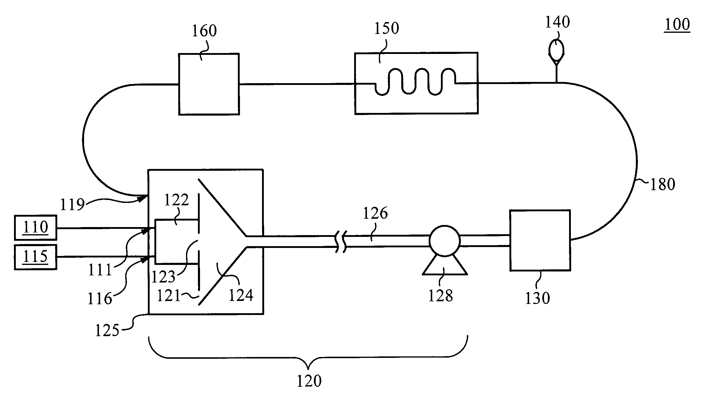
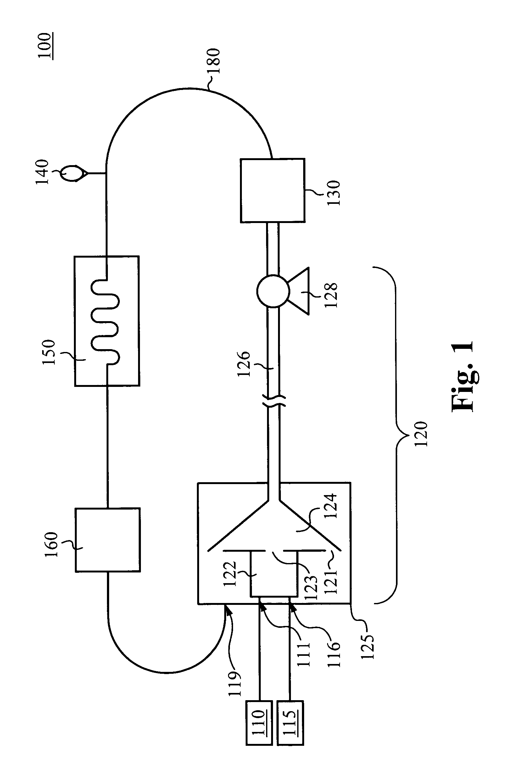
[0014]In some embodiments, a pressure relief module is fluidly coupled between the filter element and the temperature control module. This pressure relief module is configured to reduce the pressure of the filtered output if the pressure exceeds a predetermined threshold.
[0015]In some embodiments, the temperature control module comprises a heat exchanger. It is also contemplated that other means for adjusting fluid temperature can be employed.
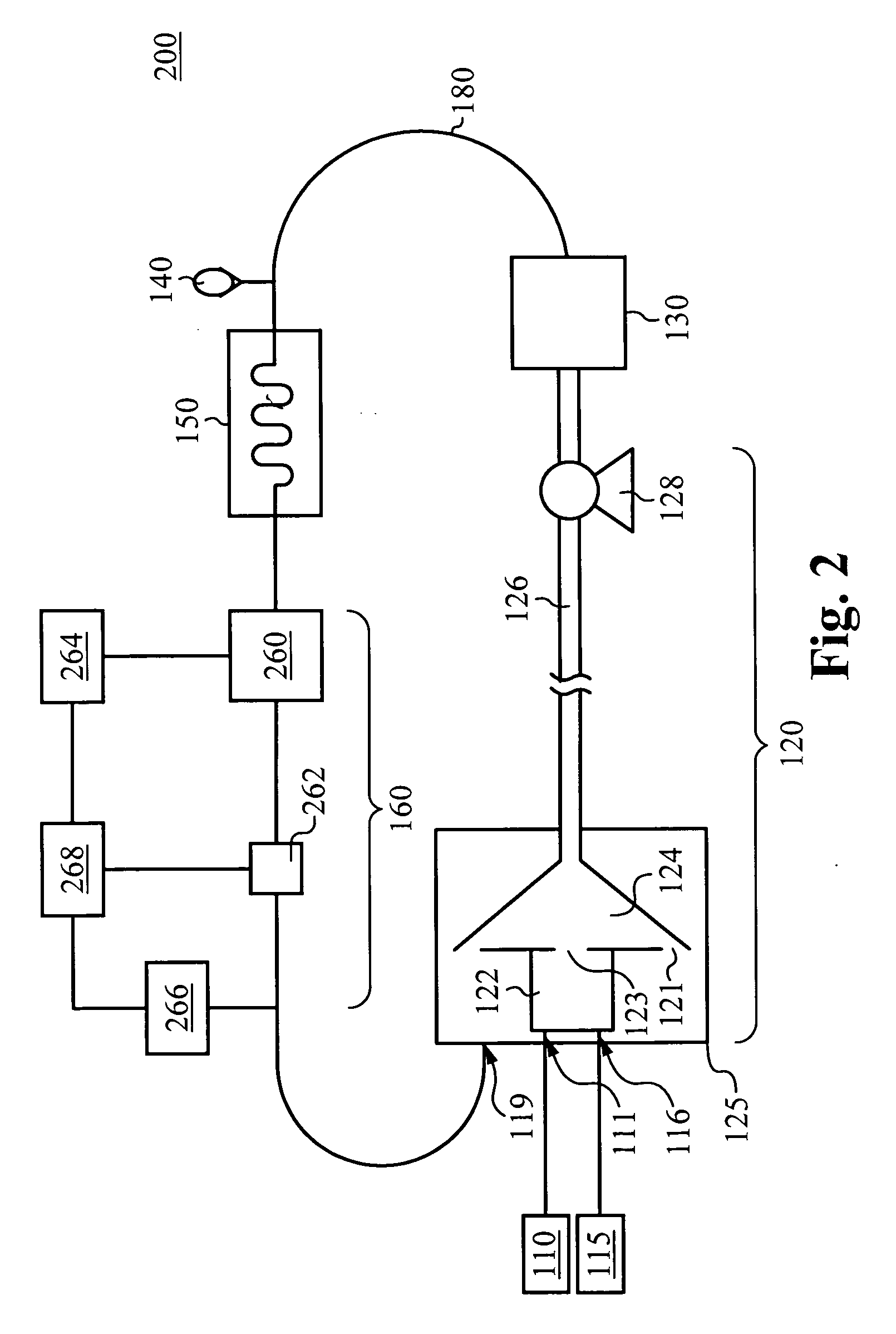
[0016]In a preferred embodiment, the content ratio control module comprises a sensor and a micro-controller communicatively connected to the sensor. The sensor is configured to sense the content ratio of the temperature-controlled, filtered output, and to produce a signal representing the sensed content ratio. The micro-controller is configured to receive the signal from the sensor and modulate the content ratio of the content-controlled, temperature-controlled, filtered output that is to be supplied to the fluid inlet of the quench chamber. This modulation is based on the received signal.
[0017]In some embodiments, the content ratio control module can further comprise a buffer reservoir fluidly coupled to the temperature control module and to the sensor. The buffer reservoir is configured to receive the temperature-controlled, filtered output from the temperature control module and to temporarily store the temperature-controlled, filtered output before the content ratio of the temperature-controlled, filtered output is modulated. The content ratio control module can also comprise a fluid relief valve fluidly coupled between the buffer reservoir and the ambient atmosphere. This fluid relief valve is configured to vent the secondary fluid from the buffer reservoir to the ambient atmosphere.
[0018]Furthermore, the content ratio control module can comprise a secondary fluid supply reservoir that stores a supply of the secondary fluid and is communicatively connected to the micro-controller. This secondary fluid supply reservoir is configured to selectively add a portion of the secondary fluid from the secondary fluid supply reservoir into the temperature-controlled, filtered output in response to a signal from the micro-controller, thereby producing the content-controlled, temperature-controlled, filtered output.
[0019]The content ratio control module can additionally or alternatively comprise a primary fluid supply reservoir that stores a supply of the primary fluid and is communicatively connected to the micro-controller. The primary fluid supply reservoir is configured to selectively add a portion of the primary fluid from the primary fluid supply reservoir into the temperature-controlled, filtered output in response to a signal from the micro-controller, thereby producing the content-controlled, temperature-controlled, filtered output.

Problems solved by technology

The unit cost of particles produced using these methods is inflated by the need to use fresh fluid for each production run.

Method used


Image

  • Fluid recirculation system for use in vapor phase particle production system
  • Fluid recirculation system for use in vapor phase particle production system
  • Fluid recirculation system for use in vapor phase particle production system

Examples


Embodiment Construction

[0026]The description below concerns several embodiments of the invention. The discussion references the illustrated preferred embodiment. However, the scope of the present invention is not limited to either the illustrated embodiment, nor is it limited to those discussed. To the contrary, the scope should be interpreted as broadly as possible based on the language of the Claims section of this document.

[0027]In the following description, numerous details and alternatives are set forth for purpose of explanation. However, one of ordinary skill in the art will realize that the invention can be practiced without the use of these specific details. In other instances, well-known structures and devices are shown in block diagram form in order not to obscure the description of the invention with unnecessary detail.

[0028]This disclosure refers to both particles and powders. These two terms are equivalent, except for the caveat that a singular “powder” refers to a collection of particles. T...


PUM

PropertyMeasurementUnit
temperatureaaaaaaaaaa
suction forceaaaaaaaaaa
pressureaaaaaaaaaa

Abstract

A method of and system for recirculating a fluid in a particle production system. A reactor produces a reactive particle-gas mixture. A quench chamber mixes a conditioning fluid with the reactive particle-gas mixture, producing a cooled particle-gas mixture that comprises a plurality of precursor material particles and an output fluid. A filter element filters the output fluid, producing a filtered output. A temperature control module controls the temperature of the filtered output, producing a temperature-controlled, filtered output. A content ratio control module modulates the content of the temperature-controlled, filtered output, thereby producing a content-controlled, temperature-controlled, filtered output. A channeling element supplies the content-controlled, temperature-controlled, filtered output to the quench chamber, wherein the content-controlled, filtered output is provided to the quench chamber as the conditioning fluid to be used in cooling the reactive particle-gas mixture.

Description

CROSS-REFERENCE TO RELATED APPLICATIONS[0001]The present application claims priority to co-pending U.S. patent application Ser. No. 11 / 110,341, filed on Apr. 19, 2005, entitled, “HIGH THROUGHPUT DISCOVERY OF MATERIALS THROUGH VAPOR PHASE SYNTHESIS” and to co-pending U.S. Provisional Application Ser. No. 60 / 928,946, filed May 11, 2007, entitled “MATERIAL PRODUCTION SYSTEM AND METHOD,” both of which are hereby incorporated by reference as if set forth herein.FIELD OF THE INVENTION[0002]The present invention relates generally to the field of particle production. More specifically, the present invention relates to systems and methods for recirculating fluid used within a vapor phase particle production system.BACKGROUND OF THE INVENTION[0003]Many vapor phase particle production systems produce mixtures of particles and fluid. Typically, these mixtures are high in temperature and thus reactive. In some systems, these mixtures are quenched via introduction of a conditioning fluid. The con...

Claims


Application Information

Patent Timeline
Patent Type & Authority Applications(United States)
IPC IPC(8): B01J19/08B01J19/00B01D46/00B01D46/42
CPCB22F9/12Y10T156/15F28D7/024F28D7/08F28D15/00F28F27/00B22F2999/00B01J19/0013Y10S623/923B01J25/00B01J25/02Y10S623/92B22F2202/13Y10T137/0391Y10T137/2076A61L2/18B22F2203/13B01J19/088B01J37/0018B01J37/349B01J37/06B01J2219/0805B01J2219/0894B01J2/16B01J35/04B01J37/0027B01J2219/0879F28C3/16
Inventor LAYMAN, FREDRICK P.
Owner SDC MATERIALS
Why Eureka
Try Eureka