Hopper with slide discharge gate and method making the same

Inactive Publication Date: 2008-11-13
SNYDER INDS
View PDF0 Cites 91 Cited by
  • Summary
  • Abstract
  • Description
  • Claims
  • Application Information

AI Technical Summary

Benefits of technology

[0011]In making a hopper container in accordance with the teachings of the present invention, the resin is deposited within the mold and the latter is securely closed and coupled to a conventional rotational molding machine. The mold is rotated on two or more axes to thoroughly distribute the resin throughout the mold, and is inserted into a heated room or chamber. Once the resin becomes molten and viscous so as to thoroughly and evenly coat the interior of the mold, the mold is cooled. After cooling the mold and the part formed therein to a sufficient temperature, the mold, typically in two or more mold sections, is removed from the rotational molding machine and separated. In one advantageous application of the present invention, the mold is configured so that the resultant molded hollow body presents an extension which is stepped in a series of progressively smaller, but similar shapes. Such an extension is useful in forming a bin outlet housing, typically located at the bottom end of the completed hopper.
[0012]Once molding of the hollow body is completed, an opening is first cut or otherwise formed in the bottom end, generally in the same shape as the cross-sectional shape of the bin outlet housing, and this cutout portion can be discarded, leaving the opening exposed. Two generally parallel, transverse cuts are then made across successive longitudinal portions of the outlet housing, forming an offset transition area cut-off piece which can be discarded, and a now separate rectangular annulus which will be used as a support for the slide gate.
[0013]A first slot is formed in the front wall of the remaining outlet housing, f

Problems solved by technology

Often, many joints are required, increasing the cost of manufacture.
Further, the construction material of the bin and of the outlet housing are often different, increasing the possibility that the contents of the bin could be adversely affected by the housing material, or that the relative properties of the materials, such as thermal expansion, may lead to problems in assembly or use.
Conventional manufacturing of dry material bin ho

Method used


Image

  • Hopper with slide discharge gate and method making the same
  • Hopper with slide discharge gate and method making the same
  • Hopper with slide discharge gate and method making the same

Examples


Embodiment Construction

[0066]The following detailed description of the invention references the accompanying drawings that illustrate specific embodiments in which the invention can be practiced. The embodiments are intended to describe aspects of the invention in sufficient detail to enable those skilled in the art to practice the invention. Other embodiments can be utilized and changes can be made without departing from the scope of the present invention. The following detailed description is, therefore, not to be taken in a limiting sense. The scope of the present invention is defined only by the appended claims, along with the full scope of equivalents to which such claims are entitled.

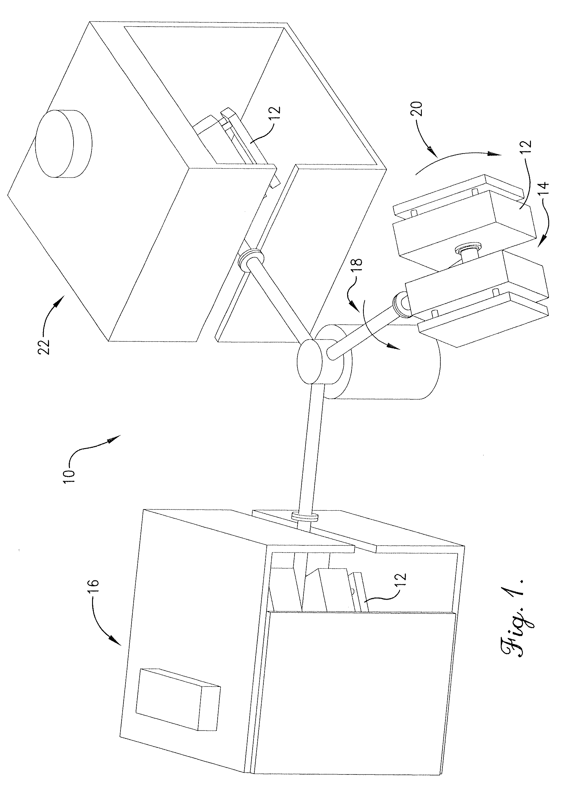
[0067]Referring now to the drawings, FIG. 1 is a schematic depiction of a rotational molding machine 10 which may be utilized in carrying out the present invention. Such rotational molding machines are known in the art and comprise a number of different stations, each of which performs a specific function. The polymer o...


PUM

PropertyMeasurementUnit
Fractionaaaaaaaaaa
Flow rateaaaaaaaaaa
Volumeaaaaaaaaaa

Abstract

A hopper bin assembly with a slide discharge gate comprises a hopper section, a slide gate housing, and a pallet. The hopper stores a volume of dry material and includes an outlet. The slide gate housing couples with the hopper and includes a discharge opening that aligns with the outlet of the hopper. A slidable gate that is coupled with the discharge opening controls the flow of material through the discharge opening. The pallet supports the slide gate housing and the hopper and includes openings that receive the forks of a forklift. A method of making at least a portion of the hopper bin assembly includes rotating a resin in a mold along two or more axes within a heated room or chamber. The mold is cooled and the part formed therein is separated into one or more sections.

Description

RELATED APPLICATION[0001]This nonprovisional patent application claims priority benefit, with regard to all common subject matter, of earlier-filed U.S. provisional patent application titled “HOPPER WITH SLIDE DISCHARGE GATE AND METHOD OF MAKING THE SAME”, Ser. No. 60 / 917,017, filed May 9, 2007. The identified earlier-filed application is hereby incorporated by reference in its entirety into the present application.BACKGROUND OF THE INVENTION[0002]1. Field of the Invention[0003]This invention concerns a method for forming an improved dry material hopper bin by rotational molding. More particularly, it is concerned with a process whereby the hopper bin and portions of the outlet valve are molded as an integral piece. This invention further concerns a method for forming two pieces of a rotationally molded storage container, such as a dry material hopper assembly, from a single mold. In addition, it is concerned with a process for interconnecting two molding compartments to form two di...

Claims


Application Information

Patent Timeline
IPC IPC(8): B67D5/06B65D25/00B29C41/04B29C41/38B65D47/00B67D7/06
CPCB29C41/06B29C41/38Y10T29/49B65D88/26B65D90/587B65D88/12
Inventor GARTON, DARWIN
Owner SNYDER INDS
Why Eureka
Try Eureka