Coating liquid for forming light emitting layer, organic electroluminescent element, method for manufacturing organic electroluminescent element, and lighting/display device

a technology coating liquids, which is applied in the direction of solid-state devices, chemistry apparatuses and processes, and light-emitting layers, can solve the problems of reducing molecular stability, reducing the luminescent efficiency of fluorescent materials, and reducing the service life of luminescent elements, so as to enhance the quantum efficiency of organic electroluminescent elements, enhance the quantum efficiency, and reduce the probability of t-t annihilation

Active Publication Date: 2018-11-27
MERCK PATENT GMBH
View PDF15 Cites 3 Cited by
  • Summary
  • Abstract
  • Description
  • Claims
  • Application Information

AI Technical Summary

Benefits of technology

[0023]The aspects according to the present invention provide a coating solution for forming a luminous layer to enhance the quantum efficiency of an organic electroluminescent element. The aspects according to the present invention also provide an organic electroluminescent element made of the coating solution for forming a luminous layer, a lighting device, a display device, and a white electroluminescent device comprising the organic electroluminescent element, and a method of producing an organic electroluminescent element.
[0024]Although the advantageous effects, mechanism, and action of the present invention are not clarified, the present inventors infer as follows.
[0025]The coating solution for forming a luminous layer according to the present invention forms a low-density coating film. Despite TADF compounds having a limited variety of substituents, the compounds are pseudo-dispersed in such a coating film to reduce the probability of T-T annihilation, enhance the quantum efficiency, and prevent shift of the peaks of light emitted to longer regions of the wavelength.
[0026]If the coating solution for forming a luminous layer according to the present invention is used in combination with a phosphorescent material and / or a host compound in preparation of organic EL elements, the phosphorescent material and / or the host compound function as fillers into the low-density portions of the coating film. Such a filler effect of the phosphorescent material and / or the host compound together with the effect of the dispersed TADF compounds achieves organic EL elements having high efficiency, low driving voltage, and prolonged service life. The coating solution for forming a luminous layer according to the present invention enhances the dispersion of the TADF compound to reduce agglomeration of luminous materials during driving of the organic EL elements, prevent a change in color of light emission, reduce formation of non-luminous centers (dark spots), and enhances the reliability of the elements.

Problems solved by technology

Such requirements reduce molecular stability, resulting in luminescent elements having shorter service lives (for example, see NPL 1).
Alight emission having such a shorter wavelength is completely traded off against a longer service life of the luminescent element, and the compatibility therebetween has not been established yet.
Unfortunately, the fluorescent materials intrinsically have a conversion rate of 50% from the lowest excited triplet energy level to the lowest excited singlet energy level.
In other words, the luminescent efficiency of the fluorescent materials is limited in principle and cannot be enhanced to be equal to the luminescent efficiency of the phosphorescent materials.
Unfortunately, the compound disclosed in PTL 2 has light emissions ranging from green to red.
Unfortunately, a reduction in the difference between the lowest excited singlet energy level and the lowest excited triplet energy level has technical difficulties in molecular design and synthesis.
Actually, introduction of a substituent into a TADF compound for the dispersion of the TADF compound in films leads to a significant reduction in luminescent efficiency, change in wavelength of light emitted, and a reduction in driving life of elements, which phenomena are not found in the common fluorescent materials and phosphorescent materials.

Method used

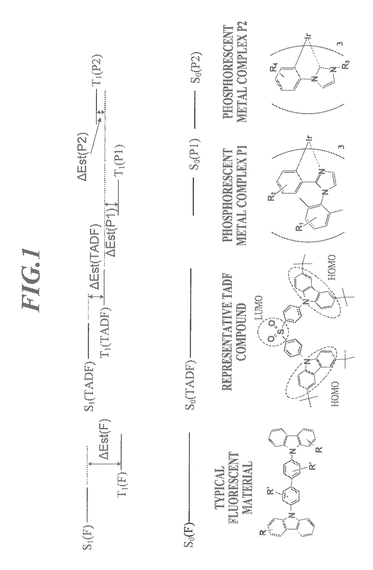
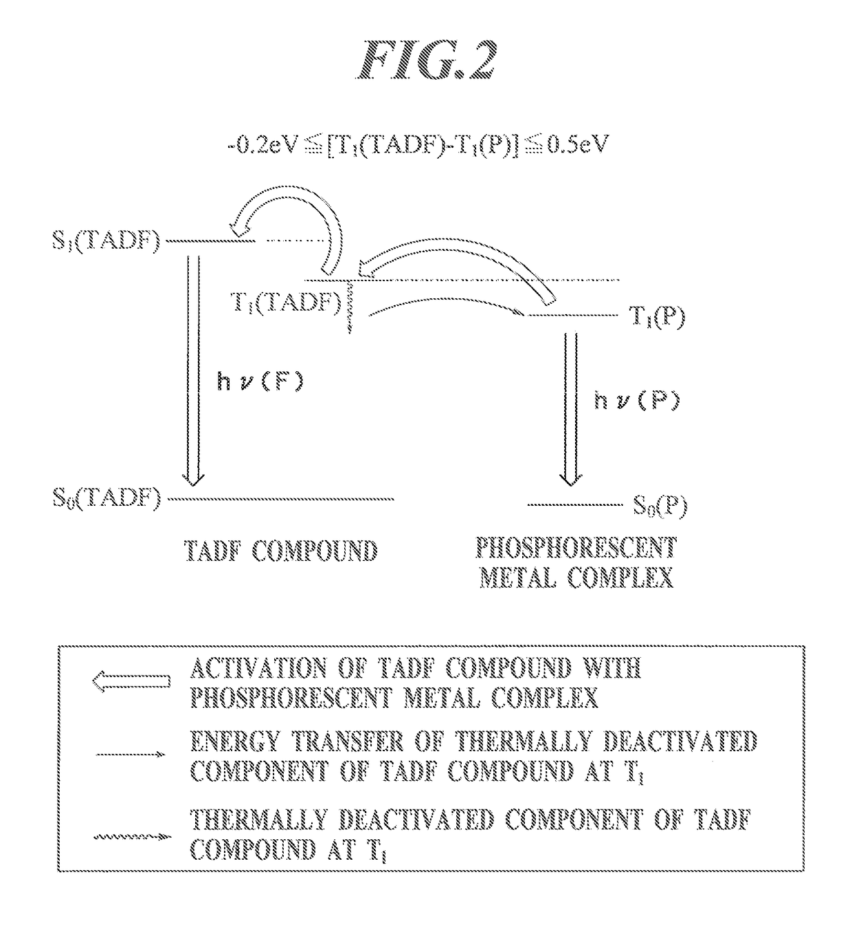
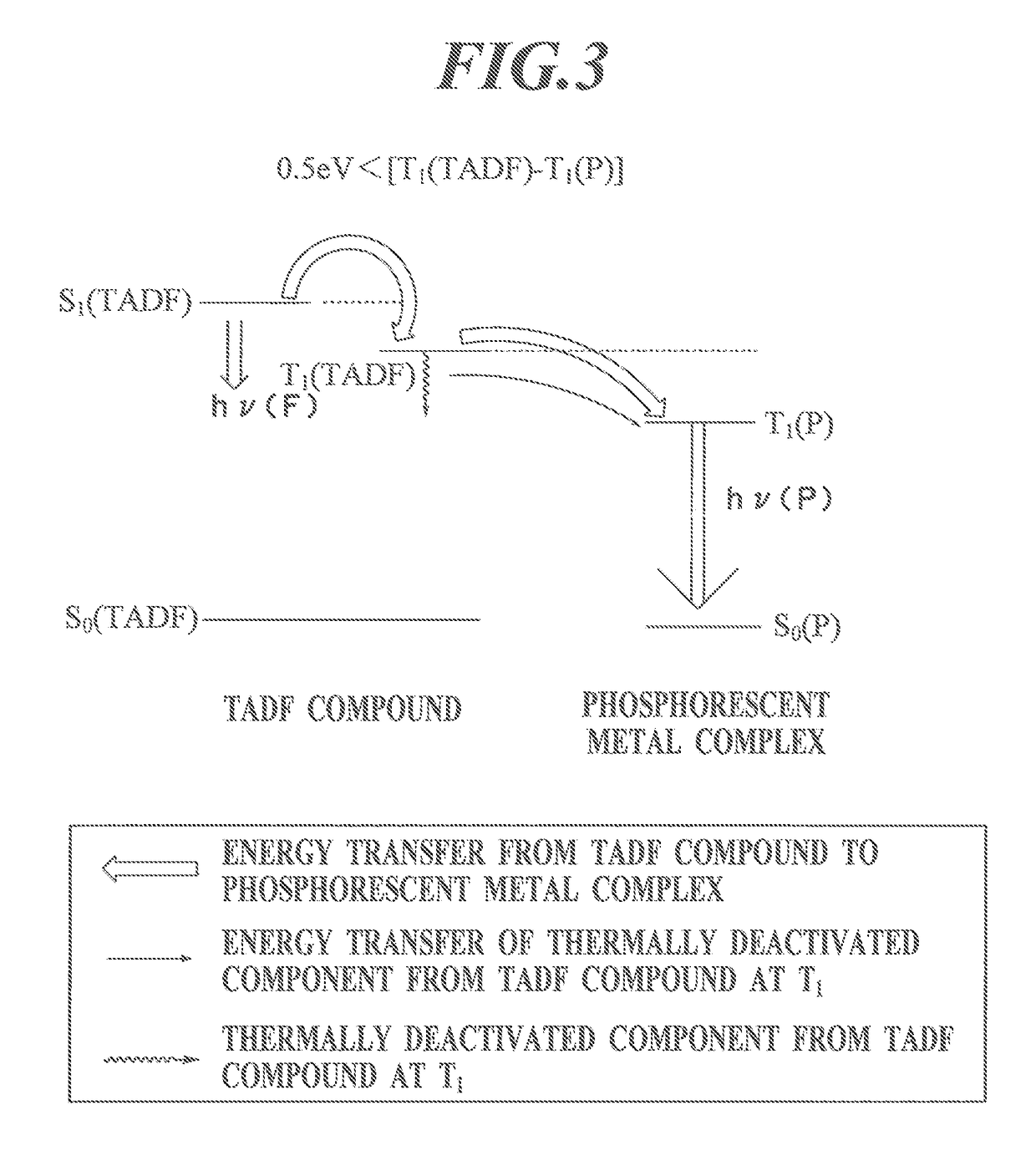

Image

  • Coating liquid for forming light emitting layer, organic electroluminescent element, method for manufacturing organic electroluminescent element, and lighting/display device
  • Coating liquid for forming light emitting layer, organic electroluminescent element, method for manufacturing organic electroluminescent element, and lighting/display device
  • Coating liquid for forming light emitting layer, organic electroluminescent element, method for manufacturing organic electroluminescent element, and lighting/display device

Examples


example 1

Preparation of Thin Film 1-1: Coating Film

[0323]A quartz substrate with dimensions of 50 mm×50 mm and a thickness of 0.7 mm was ultrasonically cleaned with isopropyl alcohol, was dried under a dry nitrogen gas stream, and was cleaned with UV / ozone for five minutes.

[0324]A diluted solution of a TADF compound 4,5-bis(carbazol-9-yl)-1,2-dicyanobenzene (2CzPN) in toluene was applied onto the substrate by spin coating at 500 rpm for 30 seconds to forma thin film. The thin film was dried at 120° C. for 30 minutes to prepare a thin film having a thickness of 40 nm.

Preparation of Thin Film 1-1: Deposited Film

[0325]A quartz substrate with dimensions of 50 mm×50 mm and a thickness of 0.7 mm was ultrasonically cleaned with isopropyl alcohol, was dried under a dry nitrogen gas stream, and was cleaned with UV / ozone for five minutes. This transparent substrate was fixed to a substrate holder of a commercially available vacuum deposition apparatus.

[0326]A TADF compound 2CzPN in an amount optimal t...

example 2

Preparation of Organic EL Element 2-1: Coating Film

(1.1) Preparation of Gas Barrier Support Substrate (Flexible Film)

[0341]A support substrate or a poly(ethylene naphthalate) film (made by Teijin DuPont Films Japan Limited, hereinafter abbreviated to PEN) was prepared. An inorganic gas barrier film made of SiOx (thickness: 500 nm) was continuously formed over the entire surface of PEN, on which an anode was formed in the subsequent step, with an atmospheric pressure plasma discharging system having a configuration described in Japanese Patent Application Laid-Open No. 2004-68143. A gas barrier flexible film was thereby prepared (oxygen permeation rate: 1×10⁻³ ml / m2·24 h·atm or less, moisture permeation rate: 1×10⁻⁶ g / m2·24 h or less).

(1.2) Deposition of Anode

[0342]Indium.tin oxide (ITO) was deposited on the gas barrier flexible film by sputtering into a film having a thickness of 120 nm. The film was patterned by photolithography into an anode.

[0343]The patterned anode had a light e...

example 3

Preparation of Organic EL Elements 3-1 to 3-22

[0361]Organic EL elements 3-1 to 3-22 were prepared as in Organic EL element 2-1 except that coating solutions containing different compounds in proportions shown in Table 8 were applied by a coating process to prepare luminous layers.

[0362]Organic EL elements 3-1 to 3-22 were prepared as in Organic EL element 2-1 except that different compounds were deposited at rates shown in Table 8 so that the deposition rates correspond to the composition ratios to prepare luminous layers. The proportion of the deposition rates of the materials was determined based on the mass proportion of the compounds other than the solvent.

[0363]

TABLE 8TADFHOSTCOM-COM-SOL-ORGANICTADFHOSTPOUND*1*2*3POUNDVENTELCOM-COM-[MASS [MASS [MASS [MASS [MASS [MASS ELEMENTPOUND*1*2*3POUNDSOLVENT%]%]%]%]%]%]NOTE3-12CzPN———S-57TOLUENE0.032———0.59899.370EXAMPLE3-24Cz IPN———S-57TOLUENE0.032———0.59899.370EXAMPLE3-34CzPN———S-57TOLUENE0.032———0.59899.370EXAMPLE3-44CzTPN———S-57TOLUEN...


PUM

PropertyMeasurementUnit
excited triplet energy levelaaaaaaaaaa
triplet energy levelaaaaaaaaaa
temperatureaaaaaaaaaa

Abstract

One objective of the present invention is to provide a coating liquid for forming a light emitting layer, which improves quantum efficiency. Another objective of the present invention is to provide: an organic electroluminescent element which is formed by means of this coating liquid for forming a light emitting layer; a lighting device, a display device and a white electroluminescent device, each of which is provided with this organic electroluminescent element; and a method for manufacturing an organic electroluminescent element. A coating liquid for forming a light emitting layer according to the present invention is used for the purpose of forming a light emitting layer, which is one of one or more organic layers held between a positive electrode and a negative electrode, and this coating liquid for forming a light emitting layer is characterized by containing a thermally activated delayed fluorescent compound.

Description

CROSS REFERENCE TO RELATED APPLICATION[0001]This Application is a 371 of PCT / JP2014 / 059651 filed on Apr. 1, 2014, which, in turn, claimed the priority of Japanese Patent Application No. JP2013-079599 filed on Apr. 5, 2013, both applications are incorporated herein by reference.TECHNICAL FIELD[0002]The present invention relates to coating solutions for forming luminous layers, organic electroluminescent elements, lighting devices, display devices, white electroluminescent devices, and methods of producing organic electroluminescent elements. More specifically, the present invention relates to coating solutions for forming luminous layers having enhanced quantum efficiency, organic electroluminescent elements, lighting device, display device, white electroluminescent devices, and methods of producing organic electroluminescent elements.BACKGROUND ART[0003]Organic electroluminescent (hereinafter written as “EL”) elements utilizing electroluminescence of organic materials (also referred...

Claims


Application Information

Patent Timeline
Patent Type & Authority Patents(United States)
IPC IPC(8): H01L51/54C09K11/06H01L51/00H01L51/50H01L27/32
CPCH01L51/0072C09K11/06H01L51/0064H01L51/0067H01L51/0073H01L51/0074H01L51/0085H01L51/0094H01L51/5012H01L51/5016H01L51/5028C09K2211/1007C09K2211/1011C09K2211/1029C09K2211/1044C09K2211/1059C09K2211/1088C09K2211/1092C09K2211/185H01L27/32H01L51/0003H01L51/0004H01L51/0005H10K59/00H10K71/135H10K85/652H10K85/342H10K50/121H10K50/11H10K2101/10H10K2101/20H10K85/6572H10K85/40H10K85/654H10K85/6574H10K85/6576H10K71/12H10K71/13
Inventor OIKAWA, KAZUHIROTAKA, HIDEOIKEMIZU, DAI
Owner MERCK PATENT GMBH
Why Eureka
Try Eureka