
Article Position Management System, Article Position Management Method, Terminal Device, Server, and Article Position Management Program

Inactive Publication Date: 2008-11-13
NEC CORP
View PDF5 Cites 27 Cited by
  • Summary
  • Abstract
  • Description
  • Claims
  • Application Information

AI Technical Summary

Benefits of technology

[0034]According to the present invention, the use of optical signal transmission means for optically transmitting positional information only to a specific region has the following effects. The place where an article is present can be determined with high accuracy, and article position management can be performed such that no article is left unchecked.BEST MODE FOR CARRYING OUT THE INVENTIONFirst Embodiment
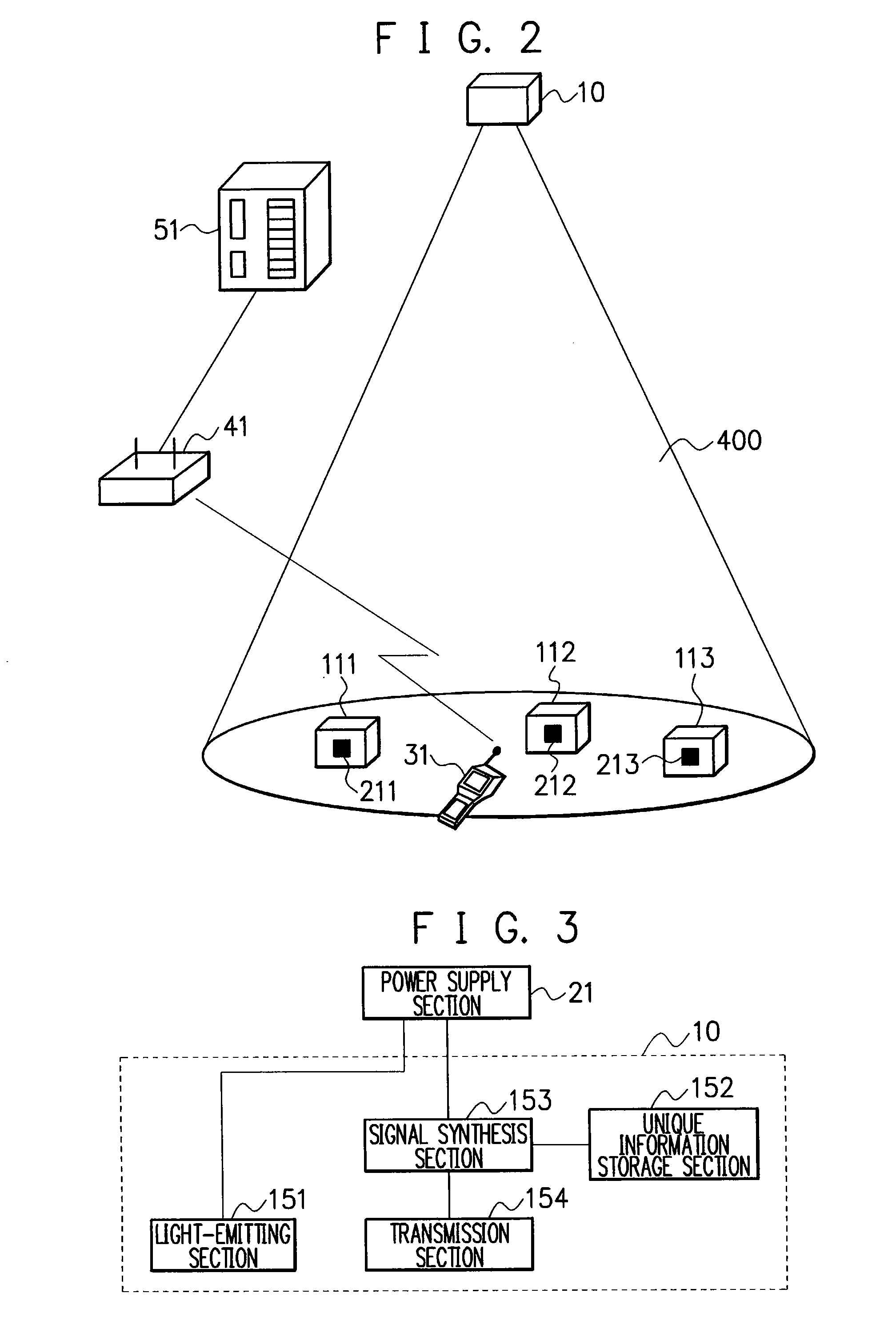
[0043]The coverage area of the transmission section 154 desirably includes that of the light-emitting section 151. If the coverage area of the transmission section 154 includes that of the light-emitting section 151, a place illuminated and lit by the illumination section 10 inevitably falls within the coverage area of the transmission section 154. Accordingly, an operator of the terminal device 31 can easily determine the coverage area of the transmission section 154. In the configuration illustrated in FIG. 4, a lens or the like may be installed outside the transmission section 154 to increase the illuminating angle.
[0047]Note that if infrared LEDs are used as the transmission section 154, the terminal device 31 can receive a piece of positional information without being affected by visible light from the light-emitting section 151. If white LEDs are used as the transmission section 154, the terminal device 31 is affected by visible light from the white LEDs of the light-emitting section 151 when it receives a piece of positional information from the white LEDs of the transmission section 154. However, since the quantity of light of the whole of the illumination section 10 (including the transmission section 154 and light-emitting section 151) differs between when the transmission section 154 transmits data of “1” and when it transmits data of “0,” the terminal device 31 can identify a piece of positional information. If infrared LEDs are used as the transmission section 154, the directivity of the infrared LEDs is preferably made equal to that of visible light from the light-emitting section 151. This is because coincidence of the illumination range of the infrared LEDs with that of the light-emitting section 151 makes it possible for an operator to easily determine the illumination range of the infrared LEDs, i.e., a positional information receivable range on the basis of the lighting range of visible light from the light-emitting section 151.
[0063]Although, in this embodiment, a piece of unique identification information (position identification information) is used as a piece of positional information, coordinate values with a predetermined position as an origin may be used as a piece of positional information. The use of coordinate values has the effect of, e.g., facilitating position management when a plurality of illumination sections are installed in a relatively wide region or the like.
[0076]The use of a cellular phone as the terminal device 31 makes it possible to make and take calls. Accordingly, if this configuration is applied to product management or the like, a manager on the server side and an operator of the transport means speak over the telephone, thereby increasing the operating efficiency.Fifth Embodiment

Problems solved by technology

However, since the strength of a radio wave sent from an active tag is generally higher than that of a radio wave sent from a passive tag, a terminal device which receives information from a place tag may receive radio waves from a plurality of place tags and may be unable to determine a place.
Even if there are many spots to which a place tag can be affixed, an active tag is not suitable for use as a fixed place tag because it has problems of expensiveness and battery drain.
If an RFID tag (regardless of whether it is a passive tag or an active tag) is used as a place tag, an operator of a terminal device cannot easily recognize whether the terminal device is in a region where communication with an RFID tag is established.
Accordingly, it is difficult to apply the system to a case where place accuracy is desired (detailed positional information is desired).

Method used


Image

  • Article Position Management System, Article Position Management Method, Terminal Device, Server, and Article Position Management Program
  • Article Position Management System, Article Position Management Method, Terminal Device, Server, and Article Position Management Program
  • Article Position Management System, Article Position Management Method, Terminal Device, Server, and Article Position Management Program

Examples


first embodiment

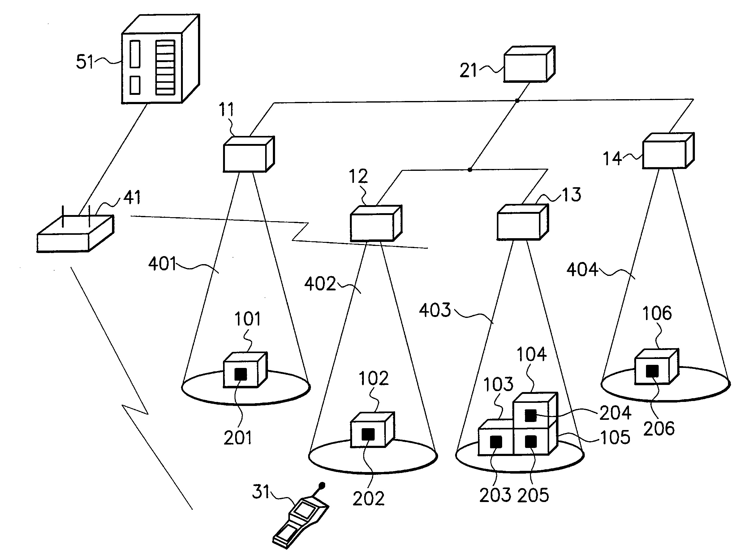
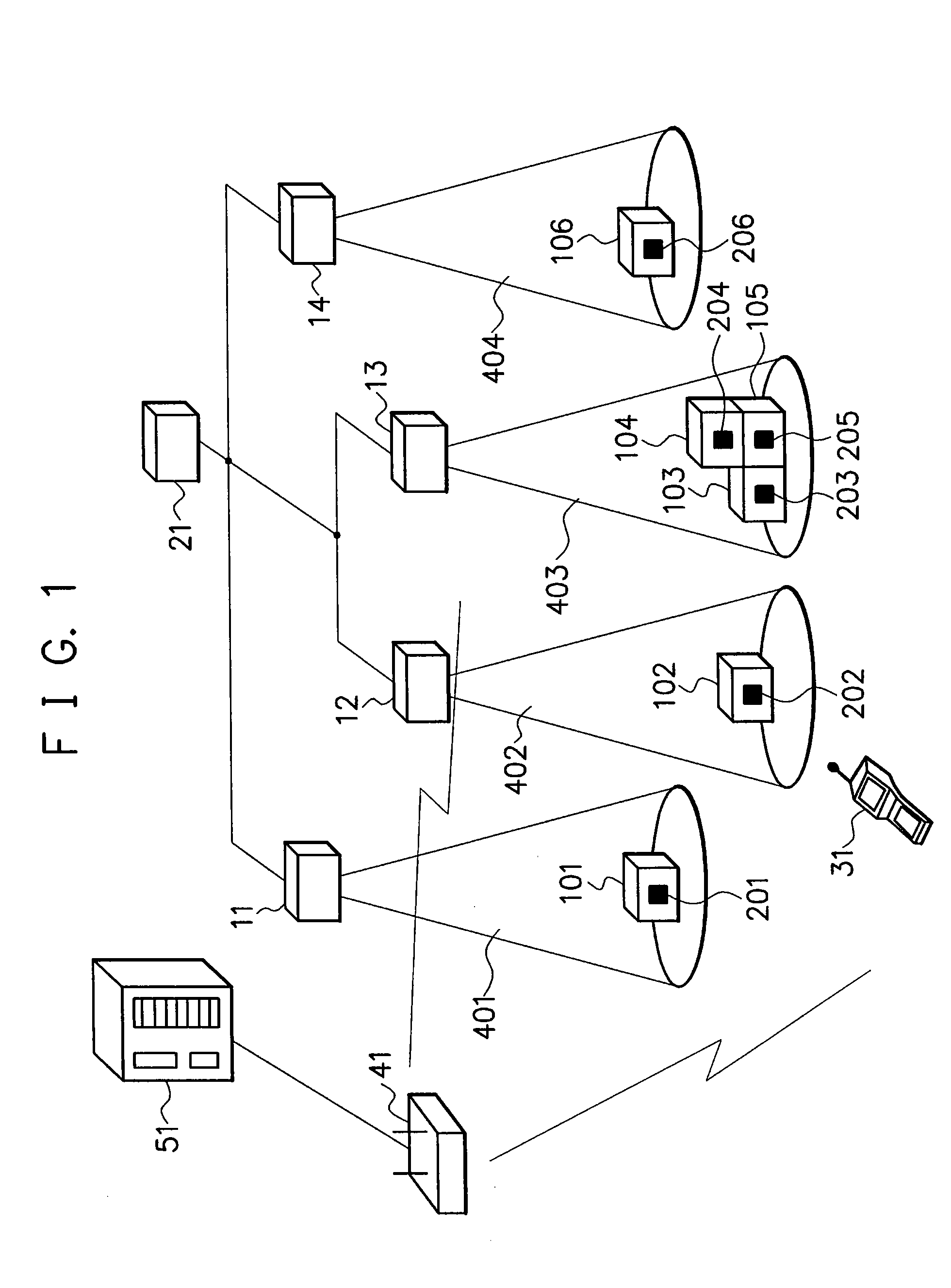
[0035]An embodiment of the present invention will be explained below with reference to the drawings. FIG. 1 is a schematic view showing a first embodiment of an article position management system according to the present invention. In the system shown in FIG. 1, illumination sections 11 to 14 which illuminate respective predetermined regions with illumination light are installed. Each of the illumination sections 11 to 14 is installed, e.g., at the ceiling of a corresponding room. The illumination sections 11 to 14 each serve as a piece of common lighting equipment instead of a fluorescent lamp or light bulb. Generally, for example, one illumination section is installed in each of regions such as rooms but a plurality of illumination sections may be installed in one region. If the plurality of illumination sections 11 to 14 are installed in one region, lighting ranges 401 to 404 of the corresponding illumination sections 11 to 14 preferably do not overlap one another.

[0036]The illum...

second embodiment

[0070]In the first embodiment, the illumination section 10 also serves as a piece of lighting equipment. However, a piece of existing lighting equipment such as a fluorescent lamp or incandescent bulb may be taken advantage of, and only a transmission section 154 may be installed. FIG. 10 is an explanatory view showing an example of the configuration of the transmission section 154 according to a second embodiment in which only the transmission section 154 is installed. In the configuration shown in FIG. 10, the transmission section 154 is composed of a plurality of infrared LEDs or white LEDs 603 to 607. The transmission section 154 is installed, e.g., on the ceiling of a room. Note that the configuration shown in FIG. 10 is merely an example and that the configuration of the transmission section 154 according to the second embodiment is not limited to this figure.

[0071]FIG. 11 is a block diagram showing an example of the configuration of an illumination section 10 according to the...

third embodiment

[0073]The embodiments described above each have taken as an example a case where asset management is performed. The present invention, however, is not limited to a system that performs asset management. For example, the present invention can be applied to management of products stored in a warehouse or the like. In this case, illumination sections 10 are installed all over the warehouse. Transport means such as a forklift equipped with a terminal device 31 itself as in the embodiments or the function of the terminal device 31 is used. An RFID tag having a unique article ID set thereon is put in advance on each of products or the like to be transported by the transport means.

[0074]When the forklift places an article in a predetermined position in the warehouse, the terminal device 31 reads a piece of positional information received from the illumination section 10 and the article ID of the unloaded article. The terminal device 31 sends the piece of positional information and article ...


PUM


Abstract

There is provided an article position management system which can determine where an article is present with high accuracy and manage the position of the article such that no article is left unchecked. Illumination sections (11-14) optically transmit pieces of positional information only to specific regions (lighting ranges (401-404)). A terminal device (31) receives the pieces of positional information transmitted from the illumination sections (11-14) and reads out article IDs from RFID tags (201-206) put on articles (101-106). The terminal device (31) sends the pieces of positional information and article IDs to a server (51) through a wireless LAN base station (41). The server (51) stores the pieces of positional information and article IDs sent from the terminal device (31) such that the pieces of positional information and article IDs are associated with each other.

Description

TECHNICAL FIELD[0001]The present invention relates to an article position management system, an article position management method, a terminal device for article position management, an article position management server, and an article position management program for managing where an asset, product, or any other article is present.BACKGROUND ART[0002]As a system which manages the position where an article is present, there is available a system in which a barcode is put on each of shelves in a warehouse and a barcode is also put on each of articles stored in the warehouse, so that when an article is stored on a shelf, information of the barcode put on the shelf and information of the barcode put on the article are read by a barcode reader (see, e.g., [1]). In this system, a terminal device with the barcode reader sends the pieces of information of both the barcodes to a management device via wireless communication. The management device stores the pieces of information of both the...

Claims


Application Information

Patent Timeline
IPC IPC(8): G08B13/14
CPCG01S1/70G01S5/16
Inventor UCHIMURA, JUNMURAYAMA, HIROKI
Owner NEC CORP
Learn More