Magnetroresistive element, method of manufacturing the same, and magnetic multilayered film manufacturing apparatus

Active Publication Date: 2008-11-13
CANON ANELVA CORP
View PDF26 Cites 19 Cited by
  • Summary
  • Abstract
  • Description
  • Claims
  • Application Information

AI Technical Summary

Benefits of technology

[0076]According to the present invention, it is possible to obtain a magnet

Problems solved by technology

However, the conventional magnetoresistive element has poor stability against heat.
Magnetoresistive elements described in Japanese Patent Laid-Open Nos. 2000-67418 (U.S. Pat. No. 6,052,263), 2003-258335, 2003-304012, and 2005-203790 have improved the thermal st

Method used


Image

  • Magnetroresistive element, method of manufacturing the same, and magnetic multilayered film manufacturing apparatus
  • Magnetroresistive element, method of manufacturing the same, and magnetic multilayered film manufacturing apparatus
  • Magnetroresistive element, method of manufacturing the same, and magnetic multilayered film manufacturing apparatus

Examples


example 1

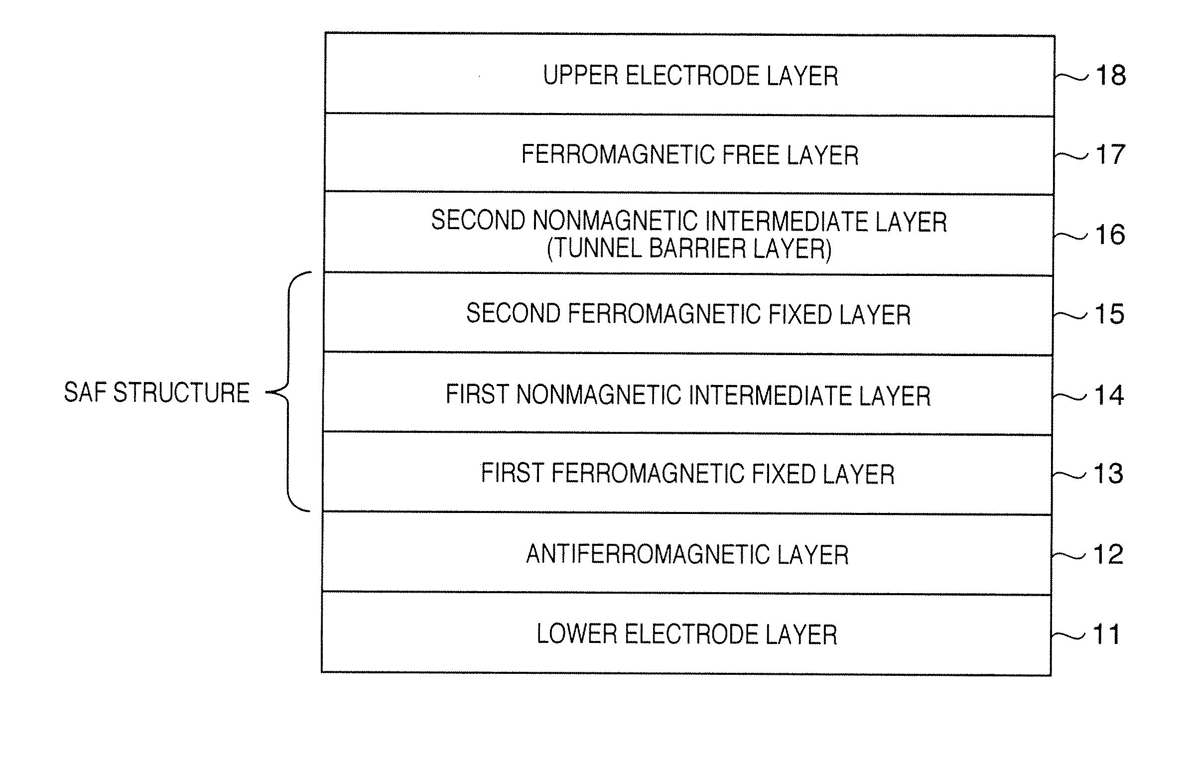
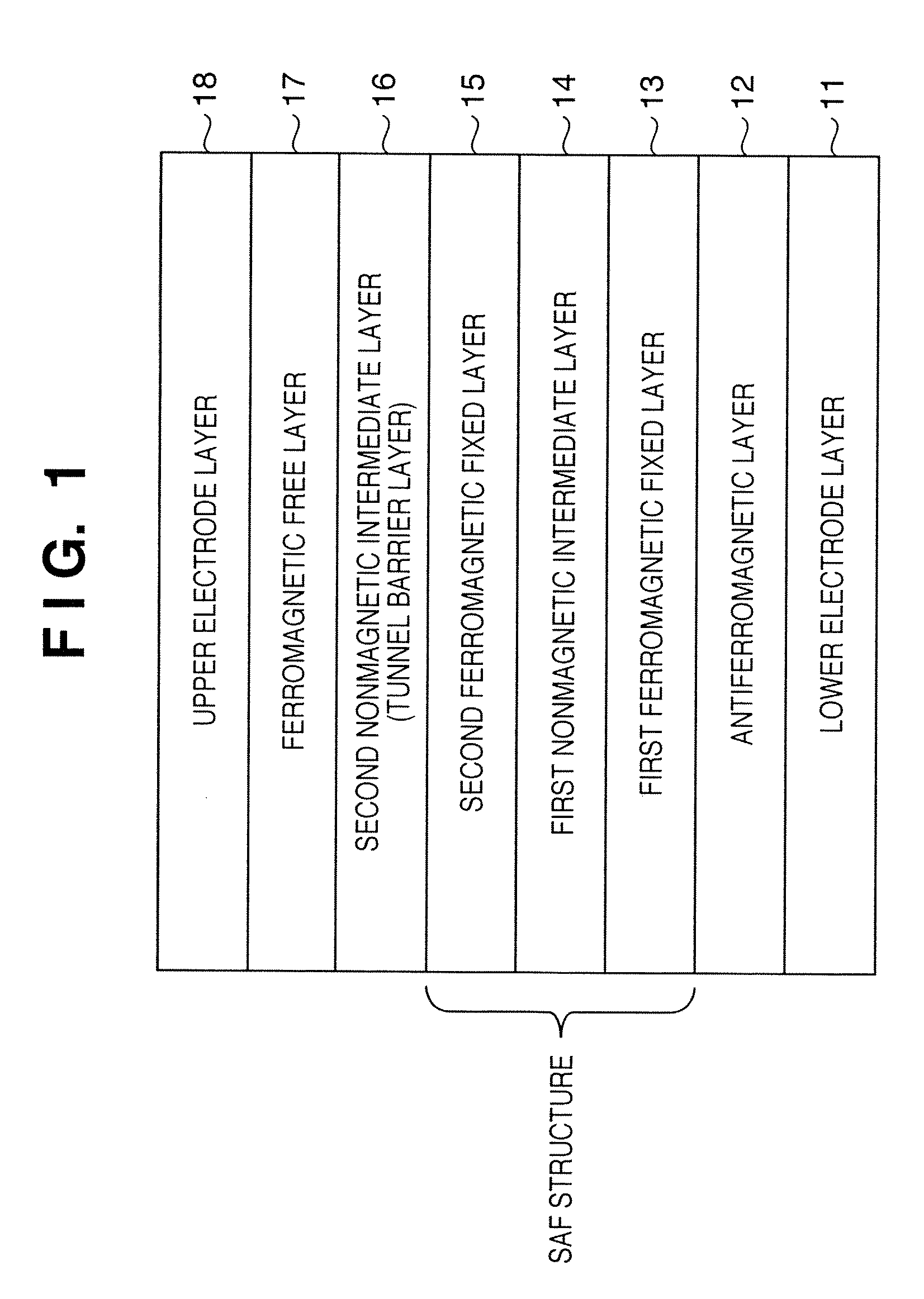
[0129]FIG. 4 is a sectional view showing the structure of a tunnel magnetoresistive element according to Example 1 of the present invention. The tunnel magnetoresistive element of Example 1 is a bottom-type tunnel magnetoresistive element corresponding to the structure shown in FIG. 1.

[0130]Referring to FIG. 4, a Ta layer 71-1 (the target 41 is used), CuN layer 71-2 (the target 42 is used), and Ta layer 71-3 (the target 41 is used) have thicknesses of 5 nm, 20 nm, and 3 nm, respectively, and form a lower electrode layer. A PtMn layer 72 (the target 51 is used) has a thickness of 15 nm and serves as an antiferromagnetic layer. A (Co70Fe30)100-XPtX layer 73 (cosputtering of the target 52 and the target 55 is used) has a thickness of 2.5 nm and serves as a first ferromagnetic fixed layer. An Ru layer 74 (the target 53 is used) has a thickness of 0.85 nm and serves as a nonmagnetic layer (nonmagnetic intermediate layer). A Co70Fe30 layer 75 (the target 55 is used) has a thickness of 2.5...

example 2

[0134]Tunnel magnetoresistive elements were manufactured in the same way as described above using iridium (Ir), osmium (Os), palladium (Pd), rhodium (Rh), and ruthenium (Ru) in place of platinum (Pt) used in Example 1, and the temperature dependence test as in Example 1 was carried out. As a result, the temperature dependence was improved, as in Example 1.

example 3

[0135]Tunnel magnetoresistive elements were manufactured in the same way as in Example 1 except that the Co70Fe30 layer 75 serving as the second ferromagnetic fixed layer of Example 1 was changed to a Co60Fe20Pt10 layer, and the temperature dependence was tested in the same way as in Example 1. Table 2 shows the result.

TABLE 2Temperature dependence of MR ratio (%)AnnealingPt content (at %)temperature05.911.71824270° C.5860606570300° C.3540505565330° C.522255760


PUM

PropertyMeasurementUnit
Antiferromagnetismaaaaaaaaaa
Structureaaaaaaaaaa
Magnetizationaaaaaaaaaa

Abstract

A magnetoresistive element includes an antiferromagnetic layer formed from a layer containing manganese, a layered magnetization fixed layer which includes a first magnetization fixed layer located over a side of the antiferromagnetic layer and formed from a layer containing a ferromagnetic material and a platinum group metal, a second magnetization fixed layer formed from a layer containing a ferromagnetic material, and a first nonmagnetic intermediate layer located between the first magnetization fixed layer and the second magnetization fixed layer, a magnetic free layer formed from a layer containing a ferromagnetic material, and a second nonmagnetic intermediate layer located between the layered magnetization fixed layer and the magnetic free layer.

Description

BACKGROUND OF THE INVENTION[0001]1. Field of the Invention[0002]The present invention relates to a magnetoresistive element such as a tunnel magnetoresistive element or a giant magnetoresistive element, a method of manufacturing the same, and a magnetic multilayered film manufacturing apparatus and, more particularly, to a magnetoresistive element such as a tunnel magnetoresistive element or a giant magnetoresistive element usable for the magnetic head of a magnetic disk drive or a magnetic random access memory, a method of manufacturing the same, and a magnetic multilayered film manufacturing apparatus.[0003]2. Description of the Related Art[0004]A conventional magnetic disk drive uses a giant magnetoresistive element or a tunnel magnetoresistive element for its magnetic head.[0005]A giant magnetoresistive element has an antiferromagnetic layer, ferromagnetic fixed layer, nonmagnetic conductive layer, and ferromagnetic free layer. A tunnel magnetoresistive element has an antiferrom...

Claims


Application Information

Patent Timeline
IPC IPC(8): G11B5/33
CPCB82Y10/00B82Y25/00B82Y40/00C23C14/568G01R33/093G11B5/3909G11B5/3932G11B2005/3996H01F10/3254H01F10/3272H01F41/302
Inventor TSUNEKAWA, KOJIDJAYAPRAWIRA, DAVID D.
Owner CANON ANELVA CORP
Why Eureka
Try Eureka