
Palladium—rhodium single-layer catalyst

Active Publication Date: 2015-10-13
UMICORE AG & CO KG
View PDF15 Cites 16 Cited by
  • Summary
  • Abstract
  • Description
  • Claims
  • Application Information

AI Technical Summary

Benefits of technology

The patent describes a new type of catalyst that has excellent lightoff performance and high thermal stability. The catalyst also has low exhaust gas backpressure and is cost-effective to produce. The active aluminum oxide and cerium / zirconium mixed oxides are introduced into the coating as pulverulent solids. The thermal stability of these oxides can be improved by adding certain elements such as iron, manganese, tin, titanium, silicon, yttrium, lanthanum, praseodymium, neodymium, samarium, and mixtures thereof. The amount of doping elements should preferably be between 1 and 15% by weight. The addition of strontium oxide or barium oxide can further improve the thermal stability of the catalyst.

Problems solved by technology

Double-layer catalysts have the disadvantage that their production is more expensive than that of single-layer catalysts.
Moreover, double-layer catalysts have a tendency to an increased exhaust gas backpressure compared to single-layer catalysts, which is at the expense of the performance of the internal combustion engines and the fuel consumption thereof.

Method used


Image

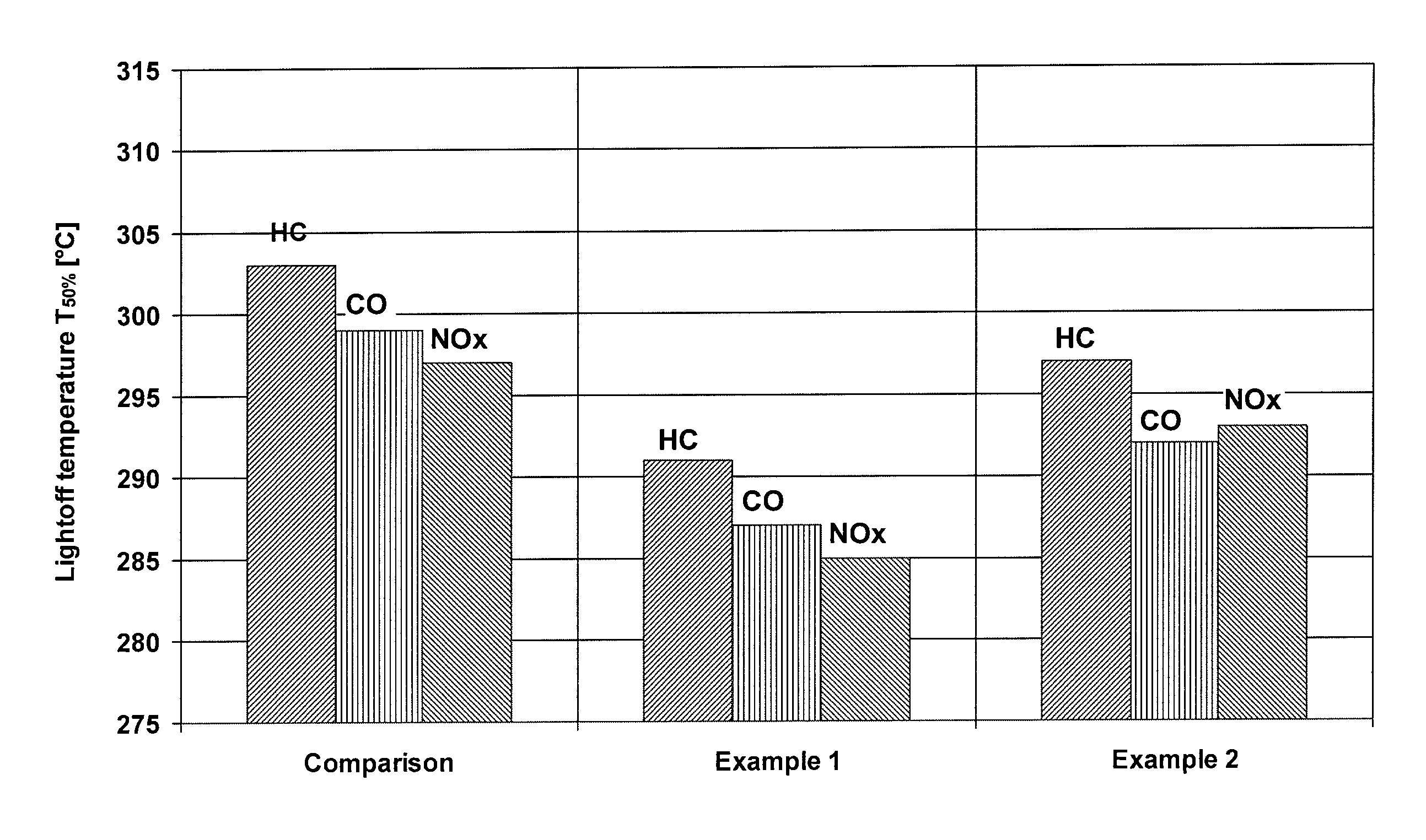
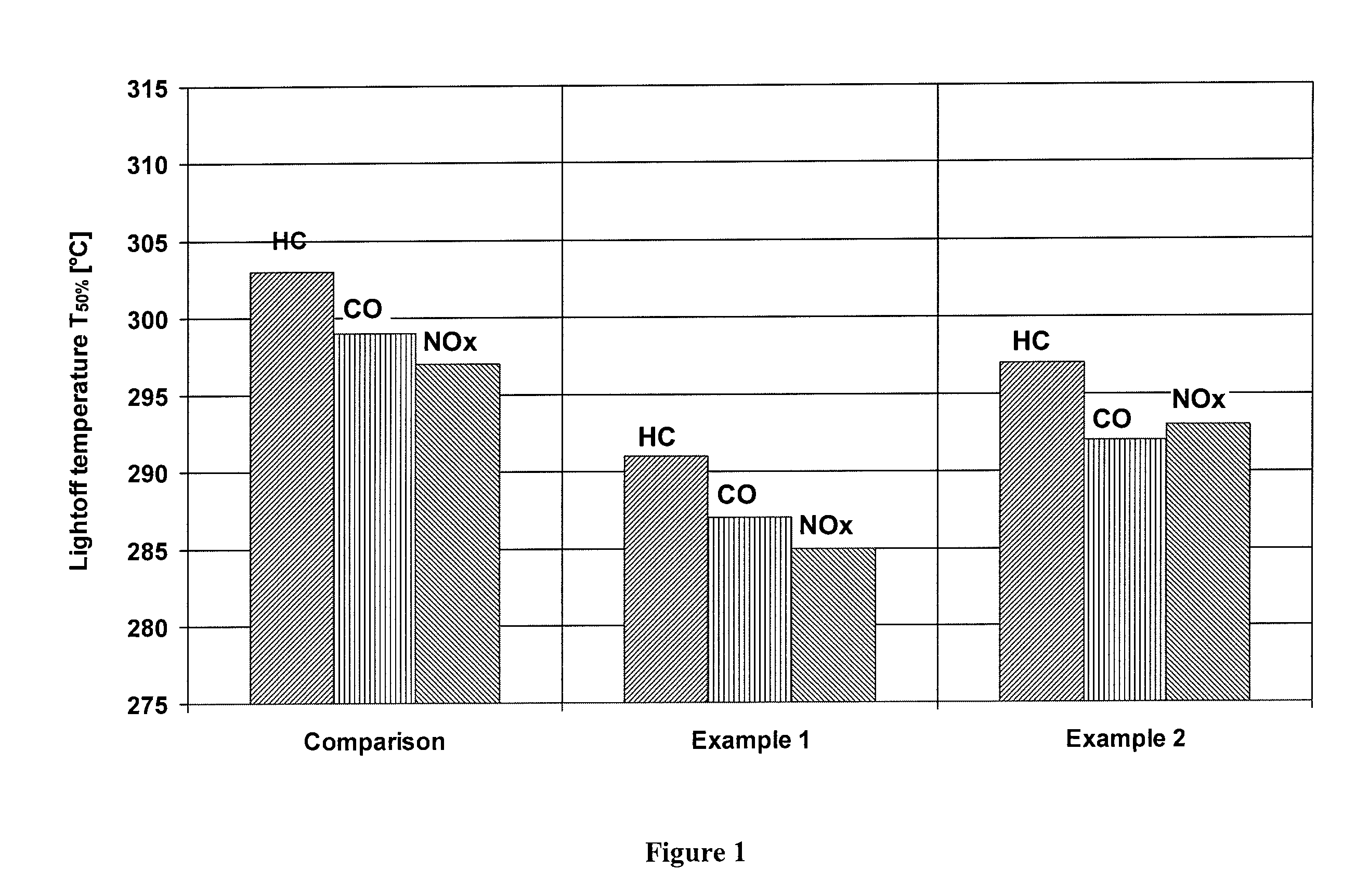
  • Palladium—rhodium single-layer catalyst
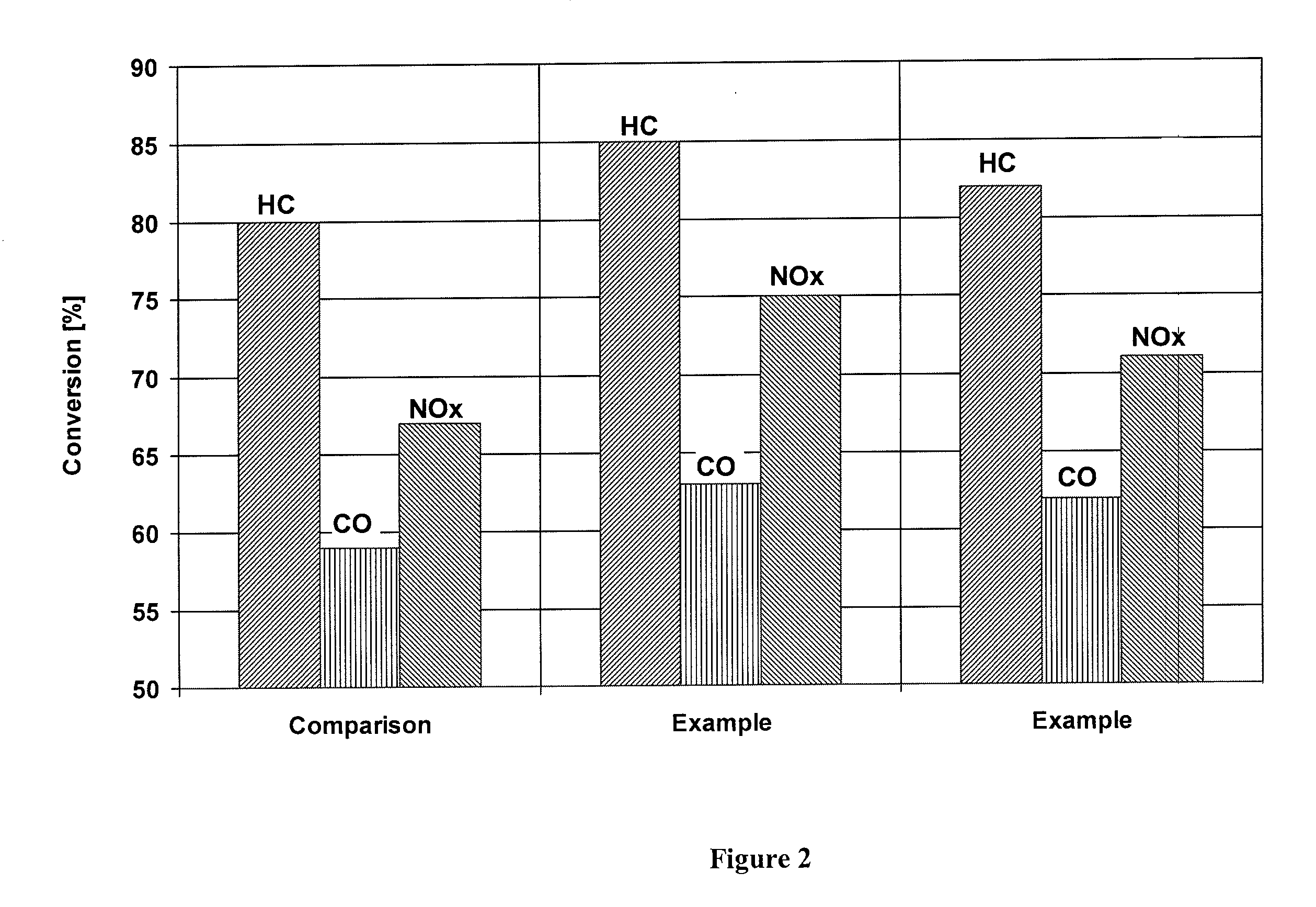
  • Palladium—rhodium single-layer catalyst
  • Palladium—rhodium single-layer catalyst

Examples


example 1

[0024]An inventive catalyst was prepared as follows:

[0025]A zirconium-rich cerium / zirconium mixed oxide (70% by weight of zirconium oxide) was suspended in water, and then rhodium nitrate was stirred into the suspension. TEAH was used to raise the pH of the suspension back to a value of about 6. Thereafter, a cerium / zirconium oxide with 50% by weight of zirconium oxide was added to the suspension, and palladium nitrate was stirred into the suspension. The pH was raised to 6 again with TEAH, before a γ-aluminum oxide stabilized with 3% by weight of lanthanum oxide was added to the suspension. Subsequently, the suspension was ground and a honeycomb was coated therewith as in the comparative example, dried and calcined. The finished catalyst contained the following amounts of coating:

[0026]

80g / lof lanthanum-stabilized aluminum oxide35g / lof first cerium / zirconium mixed oxide (70% by weight ofzirconium oxide)40g / lof second cerium / zirconium mixed oxide (50% by weight ofzirconium oxide)0.1...

example 2

[0027]A further inventive catalyst was prepared as follows:

[0028]Barium hydroxide was dissolved in water. The cerium / zirconium mixed oxide with 70% by weight of zirconium oxide was suspended in this solution, and rhodium nitrate was added to the suspension. Thereafter, the cerium / zirconium oxide with 50% by weight of zirconium oxide was dispersed in the suspension, and palladium nitrate was stirred into the suspension. After the addition of the aluminum oxide, the pH was adjusted to the value of 6 with acetic acid. Finally, the suspension was ground and a honeycomb was coated therewith, dried and calcined as in the comparative example. The finished catalyst contained the following amounts of coating:

[0029]

80g / lof lanthanum-stabilized aluminum oxide2g / lof barium oxide35g / lof first cerium / zirconium mixed oxide (70% by weight ofzirconium oxide)40g / lof second cerium / zirconium mixed oxide (50% by weight ofzirconium oxide)0.18g / lof rhodium (on first cerium / zirconium mixed oxide)0.88g / lof ...


PUM

PropertyMeasurementUnit
Percent by massaaaaaaaaaa
Massaaaaaaaaaa

Abstract

A one-layer three-way catalyst is described for the cleaning of the exhaust gases of internal combustion engines with outstanding activity and thermal stability. The catalyst comprises an active aluminum oxide, a first cerium / zirconium mixed oxide and a second cerium / zirconium mixed oxide. The first cerium / zirconium mixed oxide has a higher zirconium oxide content than the second mixed oxide. The first cerium / zirconium mixed oxide is catalytically activated with rhodium and the second cerium / zirconium mixed oxide with palladium.

Description

[0001]This application claims the benefit of International Application PCT / EP2008 / 001450 filed Feb. 23, 2008 and EP Application 07005548.8 filed Mar. 19, 2007 which are relied on and incorporated herein by reference.INTRODUCTION AND BACKGROUND[0002]The invention relates to a three-way catalyst with outstanding catalytic activity and aging stability for the cleaning of the exhaust gases of internal combustion engines.[0003]Three-way catalysts are used in large numbers for the cleaning of the exhaust gases of internal combustion engines operated under essentially stoichiometric conditions. They are capable of converting the three significant pollutants from the engine, specifically hydrocarbons, carbon monoxide and nitrogen oxides, simultaneously to harmless components. Frequently, double-layer catalysts are used, which enable a separation of different catalytic procedures and hence an optimal balance of the catalytic effects in the two layers. Catalysts of this kind are described, fo...

Claims


Application Information

Patent Timeline
IPC IPC(8): B01J23/44B01D53/94B01J21/06B01J37/02B01J35/04B01J23/63B01J23/46
CPCB01J23/44B01D53/945B01J21/066B01J23/464B01J35/04B01J37/0201B01J37/0215B01J23/63Y02T10/22B01D2255/407B01D2255/1023B01D2255/1025Y02A50/20Y02T10/12B01J35/56B01J23/46B01D53/94F01N3/10
Inventor KLINGMANN, RAOULROESCH, MARTINLINDER, DIETERRICHTER, JOERG-MICHAEL
Owner UMICORE AG & CO KG
Learn More