Methods to reduce polarization dependent loss in planar lightwave circuits

a technology of planar lightwave circuit and polarization dependent loss, which is applied in the direction of optical waveguide light guide, optical light guide, instrument, etc., can solve the problems of polarization dependent loss in optical network components affecting system performance, stress is present in the device, and the polarization dependence of the waveguide, so as to reduce polarization dependent loss, reduce the effect of polarization dependent loss

Inactive Publication Date: 2008-11-13
NEOPHOTONICS CORP
View PDF10 Cites 14 Cited by
  • Summary
  • Abstract
  • Description
  • Claims
  • Application Information

AI Technical Summary

Benefits of technology

[0013]The following presents a simplified summary of the invention in order to provide a basic understanding of some aspects of the invention. This summary is not an extensive overview of the invention. It is intended to neither identify key or critical elements of the invention nor delineate the scope of the invention. Rather, the sole purpose of this summary is to present some concepts of the invention in a simplified form as a prelude to the more detailed description that is presented hereinafter. The present invention provides OICs and methods for reducing polarization dependent loss in OICs and OICs exhibiting reduced polarization dependent loss. Generally speaking, the present invention provides a number of avenues for reducing and / or more evenly distributing stress within OICs thereby reducing polarization dependent loss.
[0014]One aspect of the invention relates to a method of reducing polarization dependent loss in an OIC by providing at least one dummy waveguide structure proximate an operable waveguide or at least one dummy metal structure proximate an operable metal structure to reduce and / or more evenly distribute stress within the OIC.
[0015]Another aspect of the invention relates to a method of reducing polarization dependent loss in an OIC by forming an OIC comprising a substrate and at least one waveguide having a first birefringence and a first optical axes; and imposing a mechanical force on the OIC to exert mechanical stress thereby changing at least one of the first birefringence and the first optical axes of the at least one waveguide to a second birefringence and a second optical axes.
[0016]Yet another aspect of the invention relates to a method of reducing polarization dependent loss in an OIC by forming a metal heater proximate at least one waveguide using a first set of metal deposition parameters; forming a conductive metal structure contacting the metal heater using a second set of metal deposition parameters; and selecting the first set of metal deposition parameters and the second set of metal deposition parameters to reduce metal stress between the conductive metal structure and the metal heater.

Problems solved by technology

A problem with OICs is polarization dependence of the waveguides, typically caused by waveguide birefringence.
Polarization dependent loss in optical network components affects a system's performance, especially when there are many components in the system.
As a result, stress is present in the device.
The stress affects the refractive index of the waveguides through the stress optic coefficients and leads to unwanted rotations of the optical axes in the couplers.
Such polarization coupling may result in increased polarization dependent loss within the device.
This may be due to excessive etch loading on the end channels during their formation.
Although it is generally desirable to reduce polarization dependent loss, an asymmetric occurrence of polarization dependent loss may be undesirable.
However, the metal structures on top of the top cladding often induce stress in the underlying waveguides.
When the stress is asymmetric, birefringence is induced undesirably rotating the optical axes.

Method used


Image

  • Methods to reduce polarization dependent loss in planar lightwave circuits
  • Methods to reduce polarization dependent loss in planar lightwave circuits
  • Methods to reduce polarization dependent loss in planar lightwave circuits

Examples


Embodiment Construction

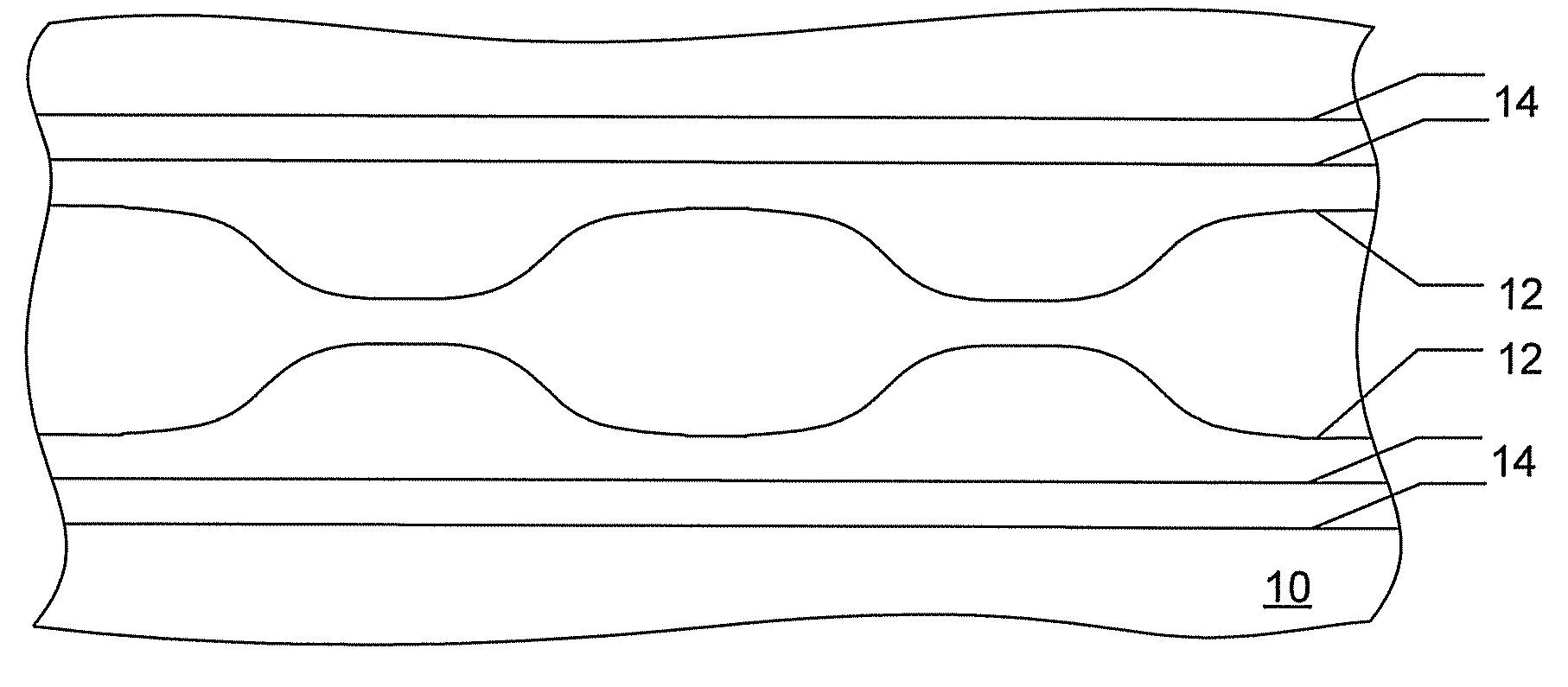
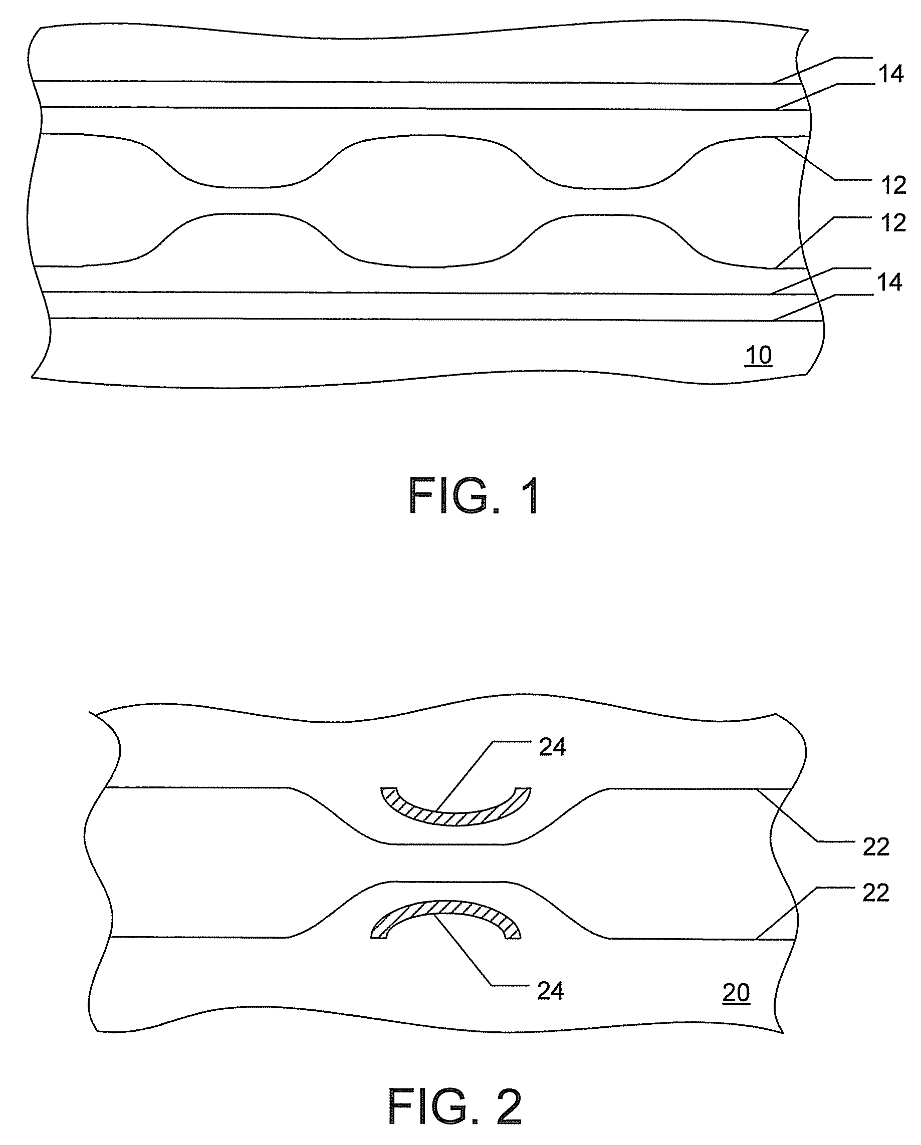
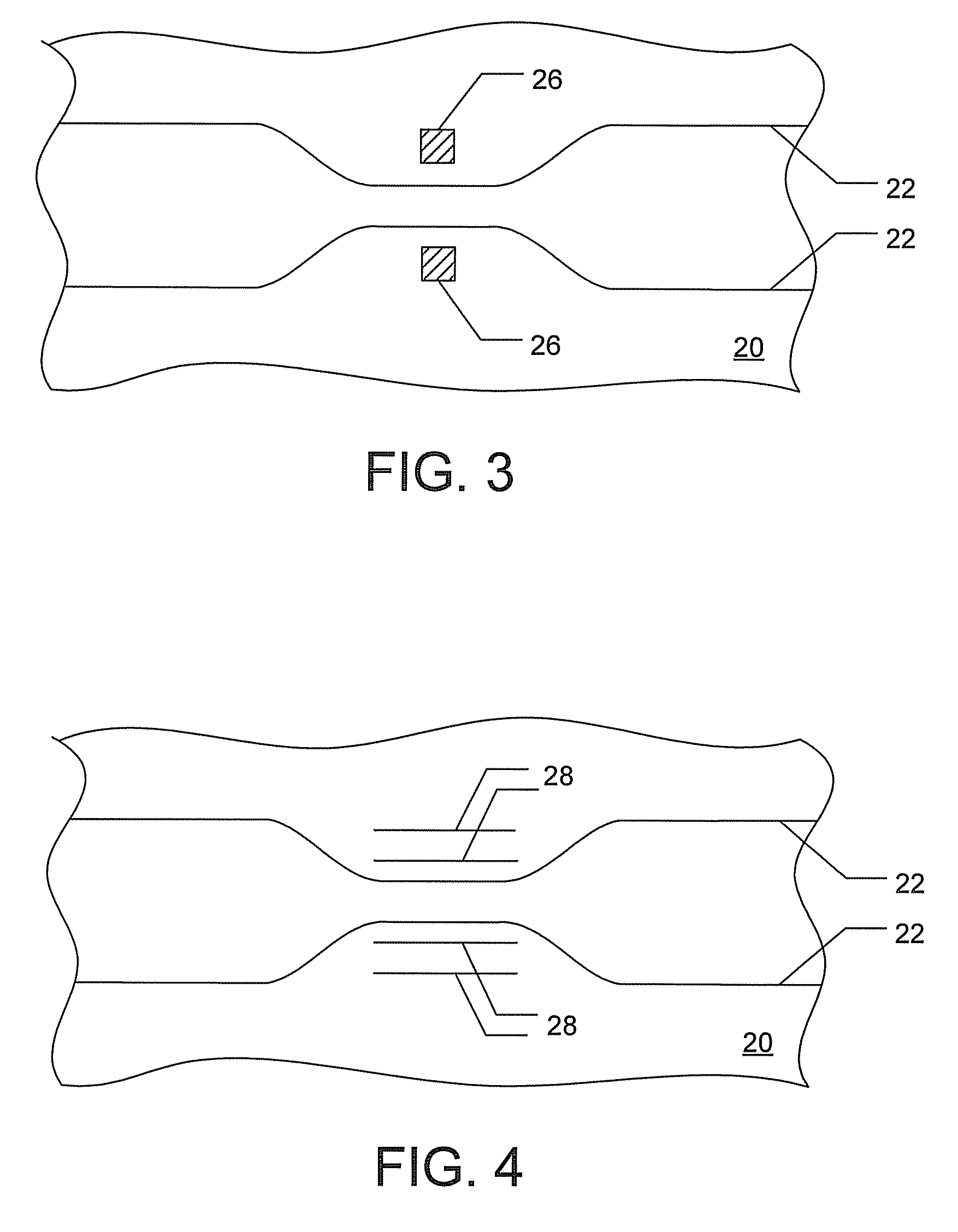
[0028]The present invention provides avenues for reducing polarization dependent loss in OICs by tailoring and / or controlling stress. Stress and polarization dependent loss in OICs can be mitigated by positioning dummy waveguide structures proximate operable waveguides functioning as couplers; by positioning dummy waveguide structures proximate operable end waveguide channels; by positioning dummy metal structures proximate operable metal structures; by maximizing the symmetry of metal structures relative to the operable waveguides; by applying mechanical stress to the OIC / waveguides; and / or by controlling the metal deposition conditions to regulate stress between adjacent metal structures.

[0029]Since stress on operable waveguides causes birefringence resulting in polarization dependent loss, reducing the stress and / or making the stress uniform upon substantially all portions of a waveguide and / or upon all waveguides in a given OIC, reduces polarization dependent loss in the OICs co...


PUM

PropertyMeasurementUnit
diameteraaaaaaaaaa
diameteraaaaaaaaaa
thicknessaaaaaaaaaa

Abstract

Polarization dependent loss may be reduced by providing at least one dummy waveguide or at least one dummy metal structure. Polarization dependent loss may also be reduced by imposing a mechanical force on the OIC to exert mechanical stress thereby changing at least one of the birefringence and the optical axes of at least one waveguide. And polarization dependent loss may be reduced by forming a metal heater using a first set of metal deposition parameters; forming a conductive metal structure contacting the metal heater using a second set of metal deposition parameters; and selecting the first set of metal deposition parameters and the second set of metal deposition parameters to reduce stress.

Description

CROSS-REFERENCE TO RELATED APPLICATIONS[0001]This application is a Division of and claims the benefit of priority to co-pending U.S. patent application Ser. No. 11 / 351,031, filed on Feb. 9, 2006, the entire contents of which are incorporated herein by reference.TECHNICAL FIELD[0002]The present invention generally relates to fabricating optical integrated circuits that exhibit reduced polarization dependent loss. In particular, the present invention relates to reducing stress within optical integrated circuits as a means to reduce polarization dependent loss.BACKGROUND[0003]As optical networks increasingly carry burgeoning Internet traffic, the need for advanced and efficient optical components rises. Optical communication systems permit the transmission of large quantities of information. Improved optical integrated circuits (OICs) are particularly needed. OICs come in many forms such as 1×N optical splitters, optical switches, wavelength division multiplexers (WDMs), demultiplexers...

Claims


Application Information

Patent Timeline
Patent Type & Authority Applications(United States)
IPC IPC(8): G02F1/295
CPCG02B6/105G02B6/12007G02B6/12023G02B6/1203G02B6/2793
Inventor LIU, ALICETRAMMEL, PAMELA SHIELL
Owner NEOPHOTONICS CORP
Why Eureka
Try Eureka