Planar lightwave circuit variable optical attenuator

a variable optical attenuator and lightwave circuit technology, applied in the field can solve the problems of large pdl in the region of high signal attenuation, limit the extinction ratio of optical switches, and large power consumption of mzi devices on si substrates, so as to reduce the polarization dependent loss of variable optical attenuators

Active Publication Date: 2005-06-23
LUMENTUM OPERATIONS LLC
View PDF4 Cites 3 Cited by
  • Summary
  • Abstract
  • Description
  • Claims
  • Application Information

AI Technical Summary

Benefits of technology

[0021] a plurality of stress relief pillars of width t less than w, integral with the main pillar, and spaced regularly at common points on opposite sides of the main pillar over the predetermined length in order to provide support to the main pillar, thereby reducing the polarization dependent loss of the variable optical attenuator.

Problems solved by technology

One of the main problems associated with silica-on-silicon MZI devices is the polarization dependence, which can limit the extinction ratio of the optical switches and result in large PDL in the region of high signal attenuation in the case of variable optical attenuator (VOA) devices.
At the same time, the power consumption of the MZI devices on Si substrate tends to be large due to the much higher thermal conductivity of Si compared to the thermal conductivity of glass.
In investigating the prior art, this teaching was found to be insufficient.
As will be discussed in detail later, it was found that a device with continuous lateral grooves or trenches does improve the heat isolation and thus reduce the switching power, but the polarization dependent loss is higher than without grooves or trenches.
Furthermore, the additional process requirements for producing an undercut waveguide are costly and reduce the strength and integrity of the device.

Method used


Image

  • Planar lightwave circuit variable optical attenuator
  • Planar lightwave circuit variable optical attenuator
  • Planar lightwave circuit variable optical attenuator

Examples


Embodiment Construction

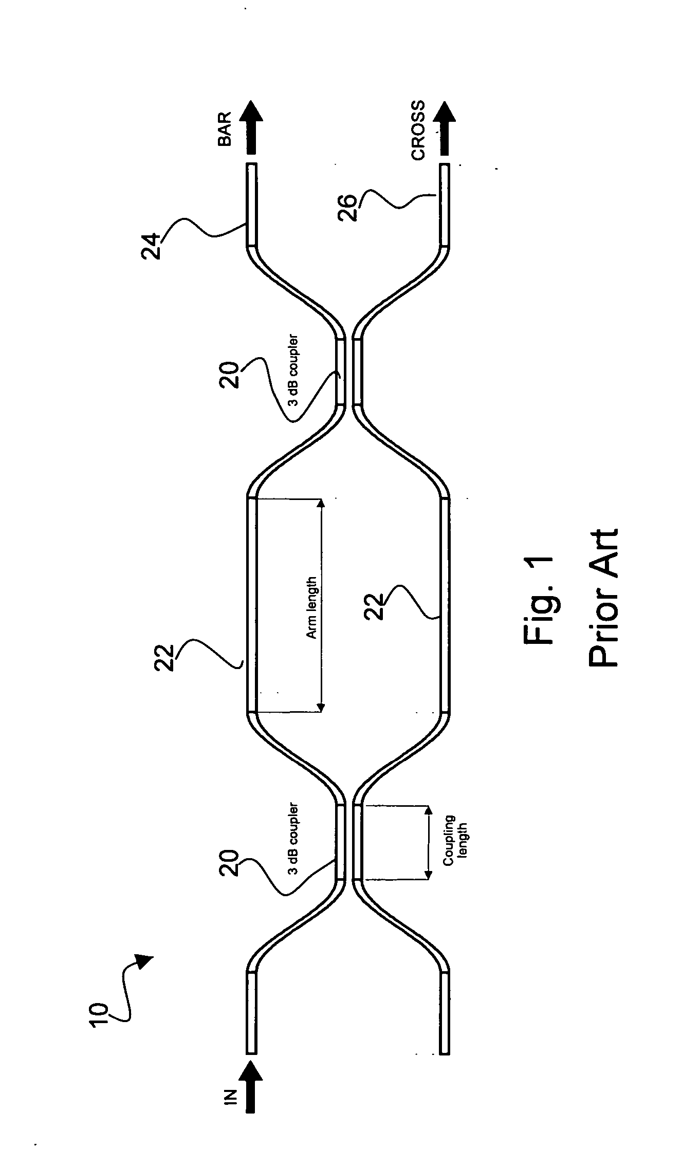
[0054] As shown in FIG. 1, a PLC MZI device 10 consists of two 3 dB directional couplers (DC) 20 or Y splitters that equally split / recombine light between two MZ arms 22. Thin film heaters 36 (see FIG. 10) are deposited on top of the upper cladding layer 31b (FIG. 10) directly above and running along the two MZ arms 22 to control the phase difference between them.

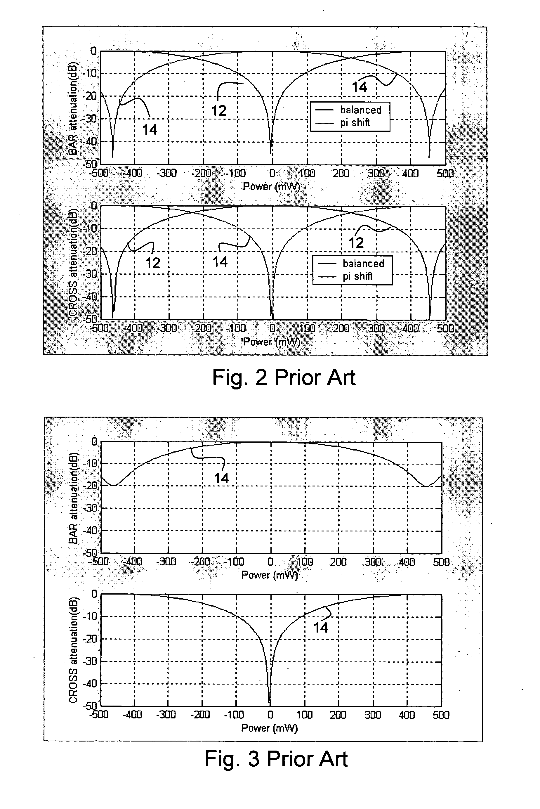
[0055] For a DC based MZI device, the two outputs from the device are denoted as BAR 24 and CROSS 26. A balanced MZI device has arms of equal length, resulting in the transmission through the device as a function of the electrical power applied to each one of the thin film heaters 36 shown in FIG. 2 as curve 12 (power applied to top heater negative, bottom heater positive). A Π shifted MZI has one of the 2 arms, for example the top one, longer than the bottom arm by an optical path length equal to Π / 2, reversing the behavior of the 2 outputs from the balanced case, as shown in FIG. 2 as curve 14. As seen in FIG. 2 the resp...


PUM

PropertyMeasurementUnit
poweraaaaaaaaaa
switching poweraaaaaaaaaa
widthaaaaaaaaaa

Abstract

The invention relates to a variable optical attenuator constructed as a Mach Zehnder planar lightwave circuit, particularly including a channel waveguide support structure for heat isolation and stress relief to reduce polarization dependent loss (PDL) and power consumption in the device. Power reduction trenches comprise longitudinal segments having small stress relief pillars of cladding material left in between them in the etching process. The waveguides of the MZI are supported by a main pillar structure and integral stress relief pillars which remain after removal of the trenches. The waveguide is surrounded by air on three sides for improved heat isolation. The performance of the present invention shows substantial improvement in PDL and extinction ratio over the prior art continuous trench design, and also, to a smaller degree, over the case where power reduction trenches are not used at all. Segmented trenches appear to allow for the lowest stress on the two waveguide arms of all the cases including no trench and trenched devices.

Description

CROSS-REFERENCE TO RELATED APPLICATIONS [0001] This application claims priority from provisional application No. 60 / 530,199 filed Dec. 17, 2003, which is incorporated herein by reference for all purposes.MICROFICHE APPENDIX [0002] Not Applicable. TECHNICAL FIELD [0003] The present application relates to a variable optical attenuator constructed as a Mach Zehnder planar lightwave circuit, particularly including a channel waveguide support structure for heat isolation and stress relief to reduce polarization dependent loss (PDL) and power consumption in the device. BACKGROUND OF THE INVENTION [0004] Recent evolution of optical communications networks emphasizes increased functionality of optical components, including wavelength filtering together with ADD / DROP capability and also power monitoring and adjustment for all the signal paths. Silica-on-silicon Planar Lightwave Circuits (PLC) is now a mature technology, producing highly stable and reliable optical components capable of accom...

Claims


Application Information

Patent Timeline
Patent Type & Authority Applications(United States)
IPC IPC(8): G02B6/12G02B6/26G02F1/01G02F1/21
CPCG02B6/12007G02B6/266G02F1/0147G02F2203/06G02F2001/0113G02F2001/212G02F1/21G02F1/0113G02F1/212
Inventor SALA, ANCA L.HARWOOD, DUNCAN W.FONDEUR, BARTHELEMYVAIDYANATHAN, ANANTHARAMANBRAINARD, ROBERT J.THEKDI, SANJAY M.NGUYEN, THOMAS T.HUTAGALUNG, IAN
Owner LUMENTUM OPERATIONS LLC
Why Eureka
Try Eureka