High-Pressure Pump, in Particular for a Fuel Injection Apparatus of an Internal Combustion Engine

Inactive Publication Date: 2008-11-13
ROBERT BOSCH GMBH
View PDF7 Cites 5 Cited by
  • Summary
  • Abstract
  • Description
  • Claims
  • Application Information

AI Technical Summary

Problems solved by technology

Due to the hydraulic forces produced, however, the outlet valve can have a tendency to vibrate in some circumstances so that the outlet valve does not remain open in a stable fashion but instead opens and closes several times, interfering with the operating behavior of the high-pressure pump and causing a significant amount of strain on the high-pressure pump due to pressure peaks that occur

Method used


Image

  • High-Pressure Pump, in Particular for a Fuel Injection Apparatus of an Internal Combustion Engine
  • High-Pressure Pump, in Particular for a Fuel Injection Apparatus of an Internal Combustion Engine
  • High-Pressure Pump, in Particular for a Fuel Injection Apparatus of an Internal Combustion Engine

Examples


Embodiment Construction

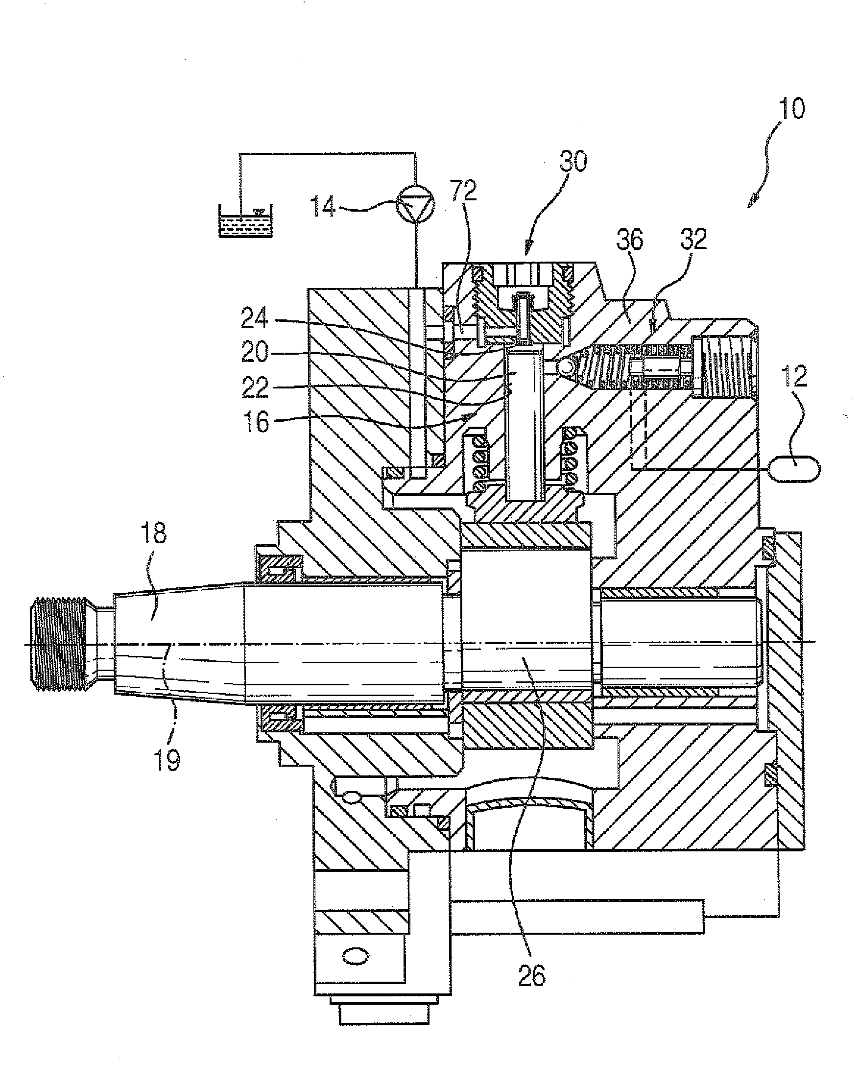
[0011]FIG. 1 shows a high-pressure pup 10 for a fuel injection apparatus of internal combustion engine that is preferably embodied in the form of an autoignition internal combustion engine. The high-pressure pump 10 delivers highly pressurized fuel to a reservoir 12 from which fuel is drawn for injection into the internal combustion engine. A fuel delivery pump 14 supplies fuel to the high-pressure pump 10. The high-pressure pump 10 has at least one pump element 16 that has a pump piston 20 driven at least indirectly into a stroke motion by a drive shaft 18 of the high-pressure pump 10. The pump piston 20 is guided in a sealed fashion in a cylinder bore 22 extending at least approximately radially in relation to the drive shaft 18 and delimits a pump working chamber 24 in the outer end region of the cylinder bore 22 oriented away from the drive shaft 18. The drive shaft 18 has a cam or a shaft section 26 eccentric to its rotation axis 19 that produces the stroke motion of the pump p...


PUM


Abstract

The high-pressure pump has at least one pump element which has a pump plunger which is driven in a reciprocating motion and defines a pump working space into which fuel is drawn in from a fuel feed via an inlet valve during the suction stroke of the pump plunger and from which fuel is displaced into a high-pressure region via an outlet valve during the delivery stroke of the pump plunger. The inlet valve and/or the outlet valve has a valve member at least approximately in the shape of a ball which interacts by means of a sealing surface with a valve seat arranged in a valve housing. By means of the valve member, in the open state, when said valve member is lifted with its sealing surface from the valve seat, a first cross section of flow is cleared between the valve member and the valve seat, and downstream of the first cross section of flow, a second cross section of flow is formed between the valve member and the valve housing. In the direction of flow between the first cross section of flow and the second cross section of flow, a third cross section of flow is formed between the valve member and the valve housing, said third cross section of flow being larger than the first cross section of flow and the second cross section of flow.

Description

PRIOR ART[0001]The invention is based on a high-pressure pump, in particular for a fuel injection apparatus of an internal combustion engine as generically defined by the preamble to claim 1.[0002]A high-pressure pump of this kind is known from DE 102004027825 A1. This high-pressure pump has at least one pump element equipped with a pump piston that is driven into a stroke motion and delimits a pump working chamber. During the suction stroke of the pump piston, fuel is drawn from a fuel inlet via an inlet valve and during the delivery stroke of the pump piston, fuel is displaced from the pump working chamber via an outlet valve into a high-pressure region, for example a reservoir. The outlet valve has a valve member at least approximately in the form of a ball, a part of whose upper surface, functioning as a sealing surface, cooperates with a valve seat situated in a valve housing. In the open state when the sealing surface of the valve member is lifted away from the valve seat, the...

Claims


Application Information

Patent Timeline
IPC IPC(8): F02M59/46
CPCF02M59/464Y10T137/7928Y10T137/7911F02M59/46F02M59/26
Inventor FUCHS, WALTERDUTT, ANDREASALEKER, JOCHENGENTE, ARNOLDSANTAMARIA, ANGELO
Owner ROBERT BOSCH GMBH
Why Eureka
Try Eureka