Method and Device for Computer Assisted Distal Locking of Intramedullary Nails

a technology of intramedullary nails and computer assisted locking, which is applied in the field of computer assisted distal locking of intramedullary nails, can solve the problems of complicated process of locating and inserting the distal interlocking screws, requiring long time and avoid repeated displacing and rearranging. , the effect of minimizing the x-ray exposure for both surgeons and patients

Active Publication Date: 2008-11-13
AO TECH AG
View PDF16 Cites 39 Cited by
  • Summary
  • Abstract
  • Description
  • Claims
  • Application Information

AI Technical Summary

Benefits of technology

[0010]One of the advantages of the present invention is due to the acquisition of only one single image, which allows to avoid a repeated displacing and rearranging of other surgical apparatus, devices and instruments and which minimizes the X-ray exposure for both the surgeon and the patient.
[0011]Another advantage is to be seen in the fact that the positioning of the X-ray device is irrespective to the orientation of the distal locking holes allowing an uncomplicated positioning of the X-ray device.
[0020]In another embodiment a data set defining a geometrical model of said distal end section is entered in the data store of the computer under step i). This allows the advantage that the geometrical model may comprise distal locking holes with a non-circular, e.g. an oval cross section and / or e.g. a conical distal end section instead of a circular cylindrical distal end section.
[0025]In yet a further embodiment the method further comprises the step of displaying a graphic representation of the first and second distal locking hole including trajectories of the axes of the first and second distal locking hole allowing a surgeon to accurately drill the holes in a bone that are necessary to insert the locking screws in the distal locking holes.

Problems solved by technology

The process of locating and inserting the distal interlocking screws is complicated by the nail deformation during insertion.
It is not possible to predict how the nail will deform accordingly.
This is achieved through a trial-and-error method and requires long time X-ray exposure for both the surgeon and patient.
This known method shows the drawback that the acquisition of the mentioned two fluoroscopic images requires a repeated and cumbersome displacing and rearranging of other surgical apparatus, devices and instruments in order to rotate e.g. the C-arm of the X-ray device from the antero-posterior direction to the lateral-medial direction.
The requirement of a fluoroscopic image in a view exactly parallel to the axes of the distal locking holes therefore shows the drawback of a very time-consuming adjustment procedure of the fluoroscope.

Method used


Image

  • Method and Device for Computer Assisted Distal Locking of Intramedullary Nails
  • Method and Device for Computer Assisted Distal Locking of Intramedullary Nails
  • Method and Device for Computer Assisted Distal Locking of Intramedullary Nails

Examples


Embodiment Construction

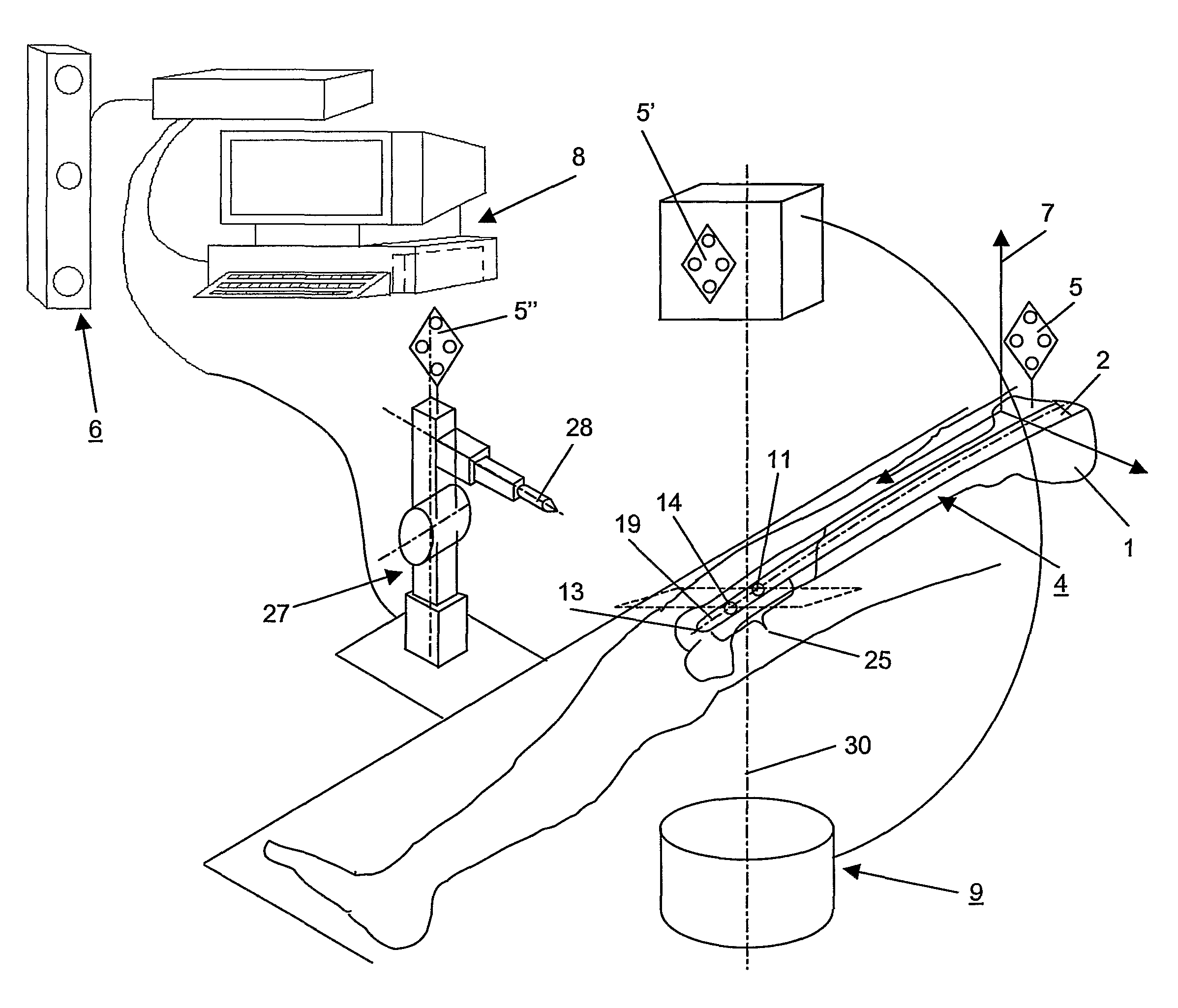
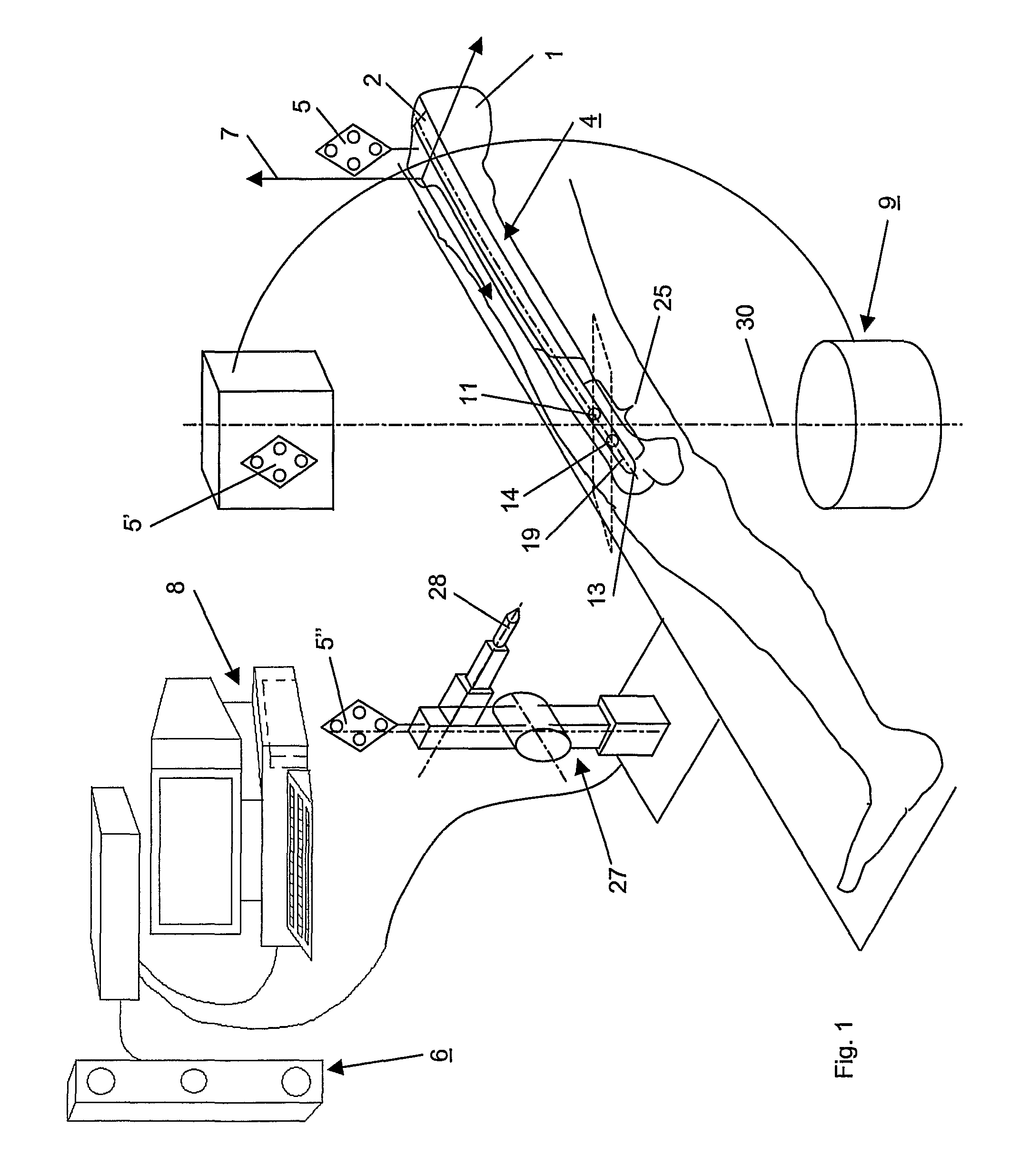
[0034]FIG. 1 shows an embodiment of the device according to the invention comprising[0035]a) a computer 8 having a data store;[0036]b) a position measurement device 6 for measuring the position and orientation of one or more dynamic reference bases 5;5′;5″ as known in the field of surgical navigation or computer assisted surgery, whereby said position measurement device 6 is connected to the computer 8;[0037]c) a dynamic reference base 5 attached at a rigid body 4 formed by an intramedullary nail 2 and the reduced fragments of a fractured bone 1;[0038]d) a C-arm X-ray device 9 being provided with a dynamic reference base 5′,[0039]e) a roboter 27 being provided with a drill bit 28 and a dynamic reference base 5″, such allowing to drill holes necessary for distal locking of an intramedullary nail 2, the position of which has been calculated by means of the computer 8 by referencing the dynamic reference base 5 attached to the rigid body 4, the dynamic reference base 5′ at the C-arm X-...


PUM


Abstract

A method for computer assisted localization of the distal locking holes (11; 14) of an implanted intramedullary nail (2) having a nail axis (19) and a first and second distal locking hole (11; 14) by A) acquiring one single image IM of the distal end section (25) of said intramedullary nail by means of an X-ray device (9) whose optical axis (30) is oriented essentially perpendicular to the nail axis (19) but irrespective to the orientation of the distal locking holes (11; 14); and B) calculating the position of the first and second hole axis (23; 20) of the first and second distal locking hole (11; 14) with respect to a three-dimensional coordinate system A-COS (7) of the implanted intramedullary nail (2).

Description

BACKGROUND OF INVENTION[0001]1. Field of Invention[0002]The invention relates to a method for computer assisted localization of the distal locking holes of an implanted intramedullary nail and to a device for the computer assisted distal locking of an intramedullary nail.[0003]2. Description of Related Art[0004]It is known that one of the most difficult steps of intramedullary nailing of e.g. femoral shaft fractures is distal locking—the insertion of distal interlocking screws, for which it is necessary to know the positions of the distal locking holes (denoted in the following as DLHs) of the intramedullary nail (IMN). The process of locating and inserting the distal interlocking screws is complicated by the nail deformation during insertion. It is known that deformation occurs in several planes due to medio-lateral (ML) and antero-posterior (AP) flexion of the intramedullary nail during its insertion. The reason for the wide variations of the insertion-related intramedullary nail ...

Claims


Application Information

Patent Timeline
Patent Type & Authority Applications(United States)
IPC IPC(8): A61B19/00A61B17/56A61B17/58
CPCA61B17/1626A61B17/1703A61B17/1725A61B19/2203A61B19/50A61B19/5212A61B19/5244A61B2019/5238A61B2019/5255A61B2019/5289A61B2034/2055A61B34/20A61B2090/364A61B90/361A61B2090/376A61B34/30A61B34/10
Inventor ZHENG, GUOYANZHANG, XUAN
Owner AO TECH AG
Why Eureka
Try Eureka