
Control System For Networked Home Electrical Appliances

Inactive Publication Date: 2008-11-13
KK TOSHIBA +2
View PDF10 Cites 94 Cited by
  • Summary
  • Abstract
  • Description
  • Claims
  • Application Information

AI Technical Summary

Benefits of technology

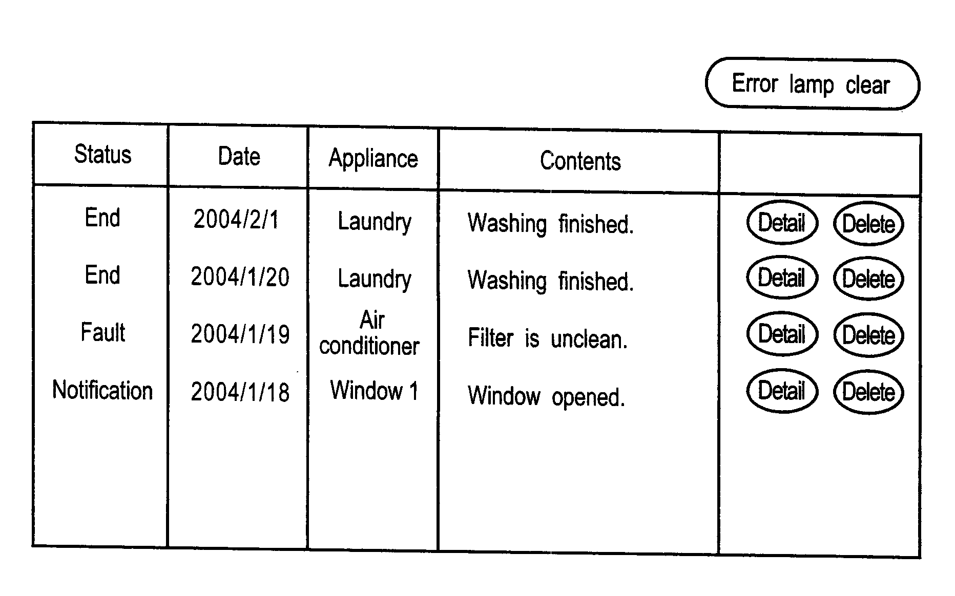
[0008]In view of the technical problems of the related art, an object of the present invention is to provide a control system for networked home electrical appliances that installs a home electrical appliance controlling ASP server as an external server in a global network such as the Internet, to allow an operation terminal in a customer's house to control a home electrical appliance through EL home server by making the external server behind the scenes transmit a GUI to the operation terminal, displaying the GUI with a browser, and enabling the GUI to be used to monitor and control the home electrical appliance.
[0018]According to the control system for networked home electrical appliances of the present invention mentioned above, an ASP server for controlling home electrical appliances is installed as an external server in a global network such as the Internet. When an operation terminal in the house of a customer is used to operate or control through a home server a home electrical appliance, the external server transmits a GUI to the operation terminal behind the scenes, so that the GUI is displayed in a browser and the home electrical appliance is operated or controlled through the GUI. The external server may hold control data and control programs for a variety of home electrical appliances. Then, without storing such data and programs in the home server, the operation terminal can be used to operate or control an optional home electrical appliance in the house through the home server. A variety of new products can be handled by newly registering control data and control programs for them to the external server. This can lighten load on the home server in operating and controlling a variety of home electrical appliances in the home.

Problems solved by technology

It is impossible to ask the customer who purchased the appliance for installing new software in the home server.
On the other hand, speed of technical innovation of household appliances is fast, and therefore, it is impractical to beforehand provide a home server with software that can wholly cover a variety of functions expected for household appliances.

Method used


Image

  • Control System For Networked Home Electrical Appliances
  • Control System For Networked Home Electrical Appliances
  • Control System For Networked Home Electrical Appliances

Examples


Embodiment Construction

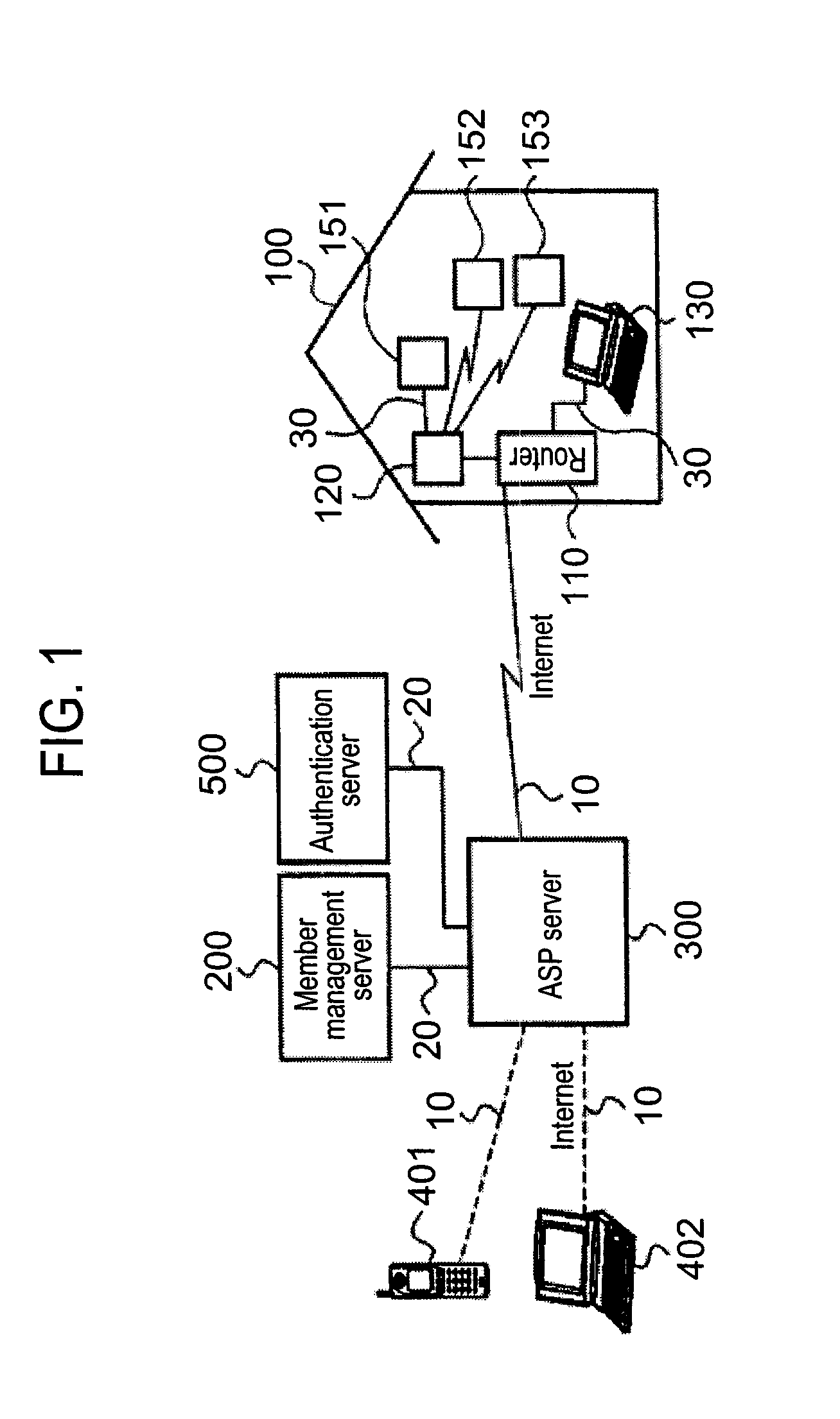
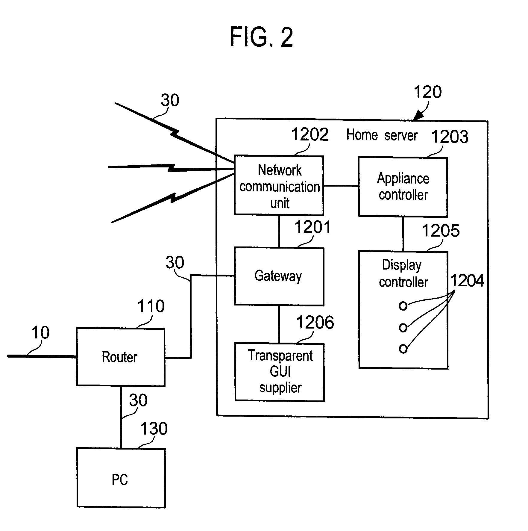
[0031]Embodiments of the present invention will be explained in detail with reference to the drawings. FIG. 1 shows a configuration of a control system for networked home electrical appliances according to an embodiment of the present invention. The control system for networked home electrical appliances of this embodiment includes a router 110, a home server 120, and various kinds of networked home electrical appliances 151 to 153 arranged in a customer's home 100, an ASP server (external server) 300 serving as a server for home electrical appliance information arranged in the Internet 10 that is a global network, a member management server 200 serving as a customer information management server, and an authentication server 500 to execute a member authentication service. The servers 200 and 500 are connected through a dedicated local network 20 to the ASP server 300. To the ASP server 300, a portable terminal 401 such as a cellular phone or a PDA and a PC 402 are externally connec...


PUM


Abstract

A network household electric control system has a household electric appliance controlling ASP server installed as an external server (300) on the Internet. When household electric appliances (150) are to be controlled from an operation terminal (130) in the house of a customer through a home server (120), the GUI is transparently transmitted from an external server to the operation terminal and is displayed with the browser so that the household electric appliances are monitored and controlled through that GUI.

Description

TECHNICAL FIELD[0001]The present invention relates to a control system for networked home electrical appliances.BACKGROUND TECHNOLOGY[0002]In recent years, home electrical appliances with communication functions, or networked home electrical appliances and techniques for using them are energetically being developed. A customer who purchased a networked home electrical appliance arranges a home server serving as a gateway to establish a wired or wireless home network and connects the home network to a router, so that the appliance is connected through the router to the Internet. Then, the customer uses a portable terminal with a browsing function, such as a cellular phone, a PDA, or a portable personal computer, or an external computer and accesses the home server and networked home electrical appliance, to remotely monitor and control the appliance.[0003]Household appliance manufacturers manufacture various kinds of networked home electrical appliances. Accordingly, a customer purch...

Claims


Application Information

Patent Timeline
IPC IPC(8): G06F3/048G06F17/00G06F15/00G06F13/00H04L12/24H04L12/28H04L29/08H04M11/00
CPCH04L12/2803H04L12/2814H04L12/282H04L41/0253H04L41/22H04L67/025G05B15/02G06F15/00H04L12/28H04M11/00
Inventor OOSAKA, NAOHISA
Owner KK TOSHIBA
Learn More