
System and method enabling circuit topology recognition with auto-interactive constraint application and smart checking

a topology recognition and automatic interaction technology, applied in the direction of symbolic schematics, instruments, cad techniques, etc., can solve the problems of inability to accurately create the large number of constraints and associated them with design objects in the first place, the complexity of the design and manufacturing process of today has significantly evolved in complexity, and the inability to enter and manage information manually

Active Publication Date: 2008-11-13
CADENCE DESIGN SYST INC
View PDF5 Cites 49 Cited by
  • Summary
  • Abstract
  • Description
  • Claims
  • Application Information

AI Technical Summary

Benefits of technology

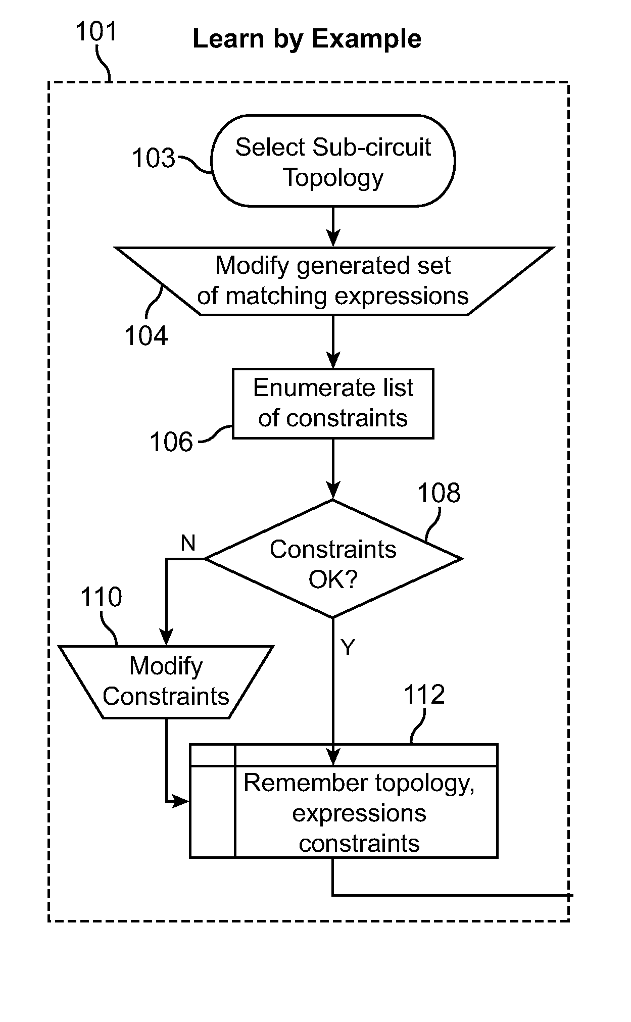
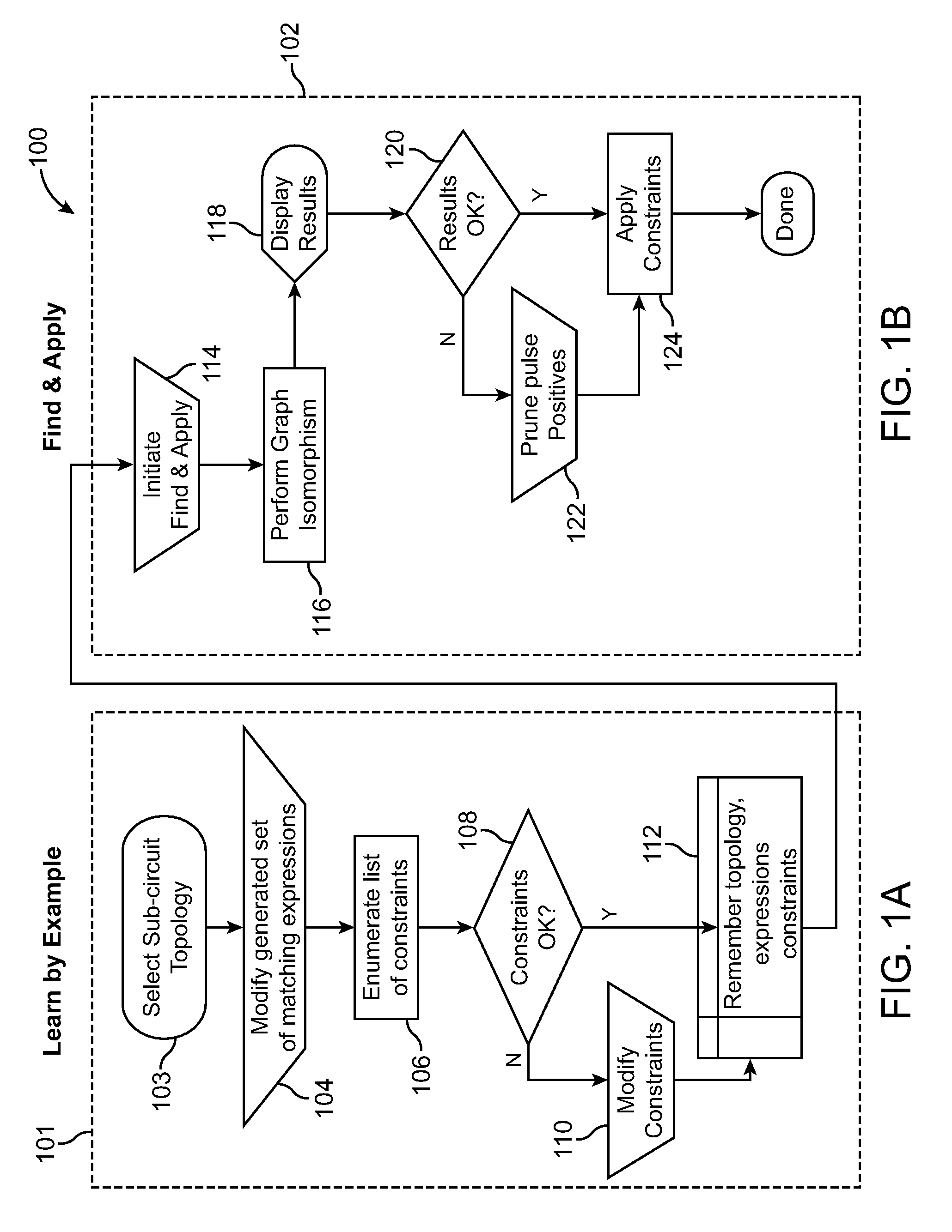
The invention is a computer-based system and method for applying constraints to sub-circuits in a circuit design. The system allows a designer to select a sub-circuit and modify its topology, which is then used to identify other sub-circuits with the same topology. The system also allows the designer to propose constraints that match the topology of the sub-circuit and decide whether to apply them to individual instances of the sub-circuit. The invention provides a more efficient and automated way to apply constraints to complex circuit designs, improving the efficiency and accuracy of the design process.

Problems solved by technology

Unfortunately, today's design and manufacturing processes have significantly evolved in complexity, which when coupled with smaller device geometries, the growth in design complexity, ever increasing numbers of design rules, and a huge numbers of constraints, have contributed to a deluge of information—far too much to be entered and managed manually.
Correctly creating the large number of constraints and associated them with design objects in the first place remains a significant problem.
All three steps can be error prone, meaning lack of accuracy, speed, and repeatability.
In the past, there often was insufficient verification that the correct constraints had been added between the right devices and / or nets, that constraints had been added consistently and uniformly, and that constraint parameters had the correct values.
Basically, a manual approach to the assignment of constraints often was fraught with errors.
Junior designers in particular are prone to making such mistakes, which can result in non-yielding or non-fictional silicon, with significant re-mask costs incurred to correct the problem.
Unfortunately, that approach is limited.
Such hard-coded induced limitations become a problem for today's rapidly changing processes, and rapidly changing design specifications during a circuit design and implementation.
Hard-coding a limited set of constraints and sub-circuits to which they may apply, is an insufficient approach to keep pace with changes and variations in design requirements after a customer has purchased and installed the EDA tool software.
Unfortunately, such automated approaches generally do not scale well to today's complex designs and processes, and such automatically inferred set of constraints often cannot keep pace with the ever evolving process requirements.
In addition, equation based approaches often are insufficient due to attempts to model all circuit behaviors to high order polynomials (first or second order polynomials are insufficient in many cases), including non-essential behaviors, and then to attempt to appropriately constrain those.
Other problems often associated with a fully automated approach to constraint assignment include errors resulting in either under or over-constrained designs, and software performance issues, as the algorithms often do not scale well to the vast number of constraints sometimes employed in today's high performance analog circuits for example, limiting the usefulness of such algorithms.

Method used


Image

  • System and method enabling circuit topology recognition with auto-interactive constraint application and smart checking
  • System and method enabling circuit topology recognition with auto-interactive constraint application and smart checking
  • System and method enabling circuit topology recognition with auto-interactive constraint application and smart checking

Examples


Embodiment Construction

[0047]The following description is presented to enable any person skilled in the art to make and use a computer implemented system and method of interactive application of constraints to sub-circuits in a circuit design stored in a computer readable medium in accordance with embodiments of the invention, and is provided in the context of particular applications and their requirements. Various modifications to the preferred embodiments will be readily apparent to those skilled in the art, and the generic principles defined herein may be applied to other embodiments and applications without departing from the spirit and scope of the invention. Moreover, in the following description, numerous details are set forth for the purpose of explanation. However, one of ordinary skill in the art will realize that the invention might be practiced without the use of these specific details. In other instances, well-known structures and processes are shown in block diagram form in order not to obsc...


PUM


Abstract

A computer implemented method is provided for interactive application of constraints to sub-circuits in a circuit design stored in a computer readable medium, comprising: receiving from a first designer a selection of a sub-circuit; receiving from the first designer a constraint; producing an information structure in computer readable medium that associates a graph representing a topology of the selected sub-circuit with the received constraint; using the graph to identify sub-circuit instances in the circuit design having the same topology as the selected sub-circuit; receiving from a second designer a selection of the information structure; presenting to the second designer one or more of the identified sub-circuit instances and the received constraint; and receiving from the second designer instruction as to application of the received constraint to one or more of the presented sub-circuit instances.

Description

BACKGROUND OF THE INVENTION[0001]1. Field of the Invention[0002]The invention relates to the design of electronic circuits and more particularly to association of constraints with design objects in electronic circuit designs.[0003]2. Description of the Related Art[0004]Electronic Design Automation (EDA) tools are computer software programs used to design electronic circuits. A suite of EDA tools may be used to convert a circuit design idea to a physical design including logic gates, circuit components and their interconnections. A circuit designer typically uses an EDA tool to create a schematic design of a circuit. The designer may use other FDA tools from the suite to convert the schematic to a physical layout, which specifies the shapes, positions, and dimensions of semiconductor and conductor materials such as silicon and metal. The EDA design tools can be used to in essence, translate a schematic design to a physical layout using layout rules, which specify, for example, that a...

Claims


Application Information

Patent Timeline
Patent Type & Authority Applications(United States)
IPC IPC(8): G06F17/50
CPCG06F17/5045G06F2217/74G06F30/30G06F2111/12
Inventor DENNISON, IAN CAMPBELLBAKER, MARKARSINTESCU, BOGDANO'RIORDAN, DONALD JOHN
Owner CADENCE DESIGN SYST INC
Learn More