Thermal Flowmeter
a flowmeter and flow rate technology, applied in the field of thermal flowmeters, can solve the problems of affecting the accuracy of thermal flowmeters, so as to suppress the degradation of characteristics and maintain high measurement accuracy over a long period of time.
- Summary
- Abstract
- Description
- Claims
- Application Information
AI Technical Summary
Benefits of technology
Problems solved by technology
Method used
Image
Examples
first embodiment
[0032]First, the following describes the basic configuration and operation principle of a thermal flowmeter according to the present invention.
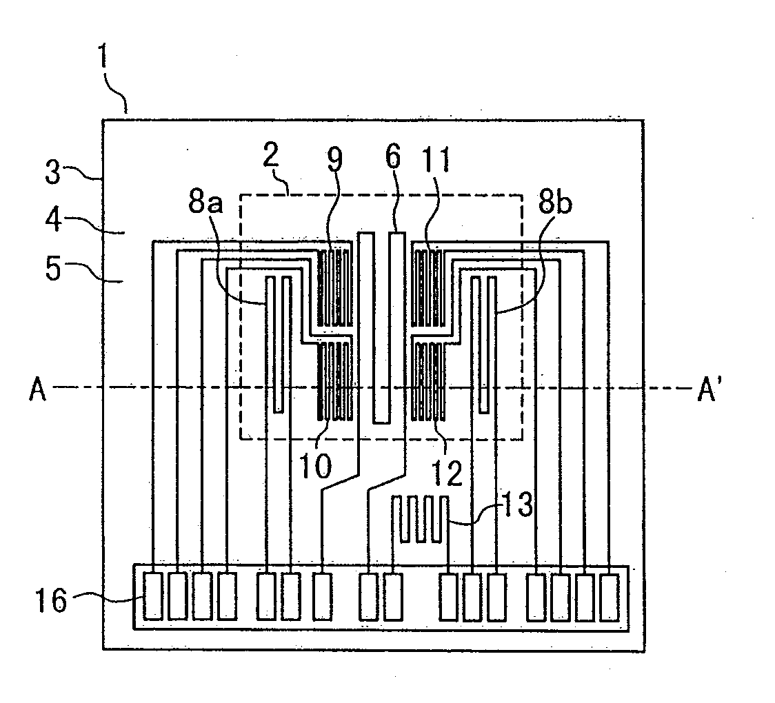
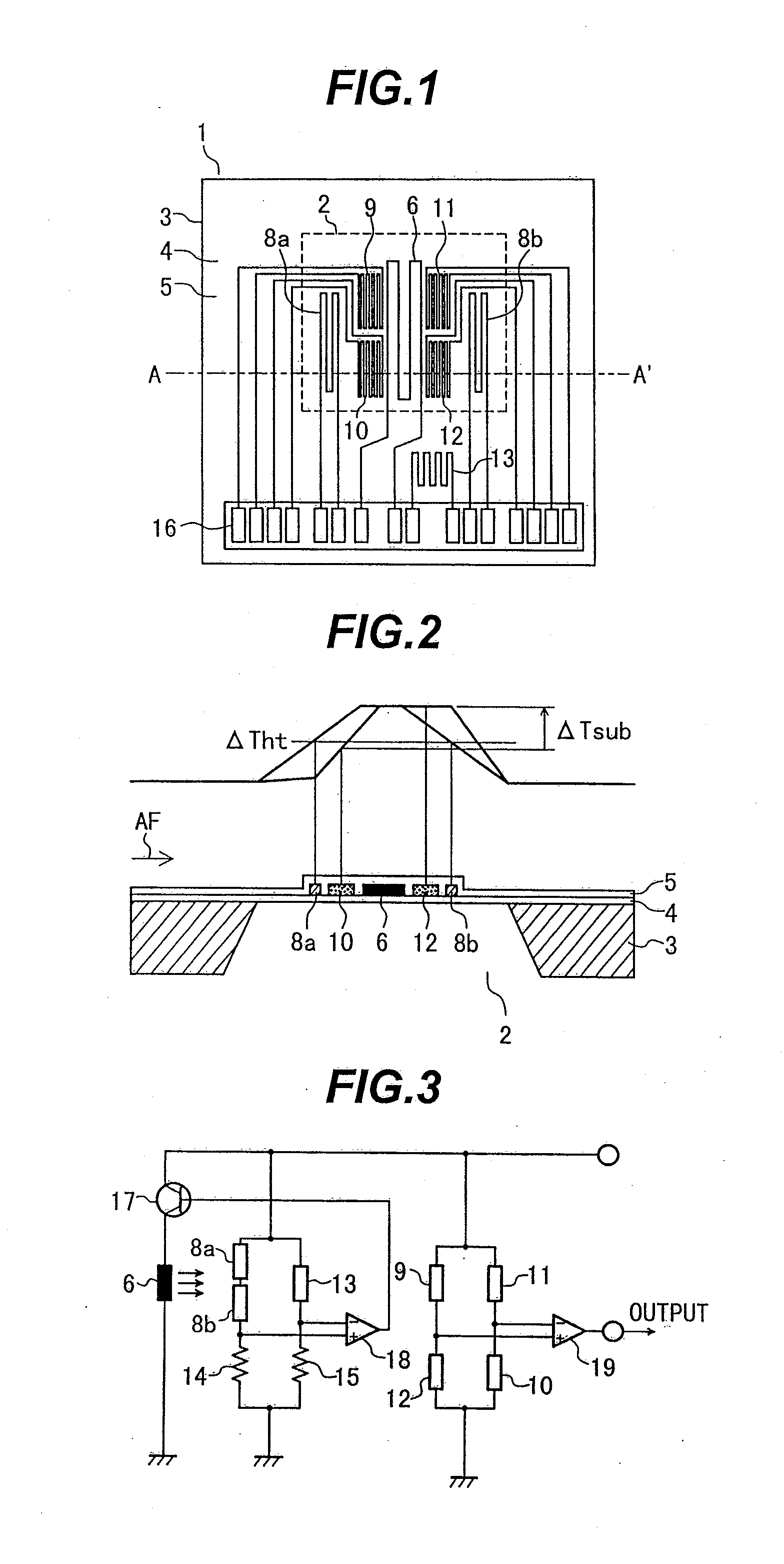
[0033]FIG. 1 is a plan view of a sensor device 1 of the thermal flowmeter according to the first embodiment of the present invention. FIG. 2 depicts a cross-section along the line A-A′ in FIG. 1 and shows temperature distributions across a diaphragm part 2.
[0034]In FIG. 1 and FIG. 2, the substrate 3 of the sensor device 1 is made of silicon, ceramic or other higher heat conductive materials. An insulation film 4 is formed on the substrate 3, and then the substrate 3 is etched from its back side so as to form the diaphragm part 2 under the insulation film 4.
[0035]On the surface of the diaphragm part 2, a heater resistor 6 is formed. This heater resistor 6 is heated so that its temperature is higher than that of an air stream AF (fluid flow to be measured) by a certain degree. In addition, temperature difference sensors 9, 10, 11 and 12, which ...
second embodiment
[0063]The following describes the present invention.
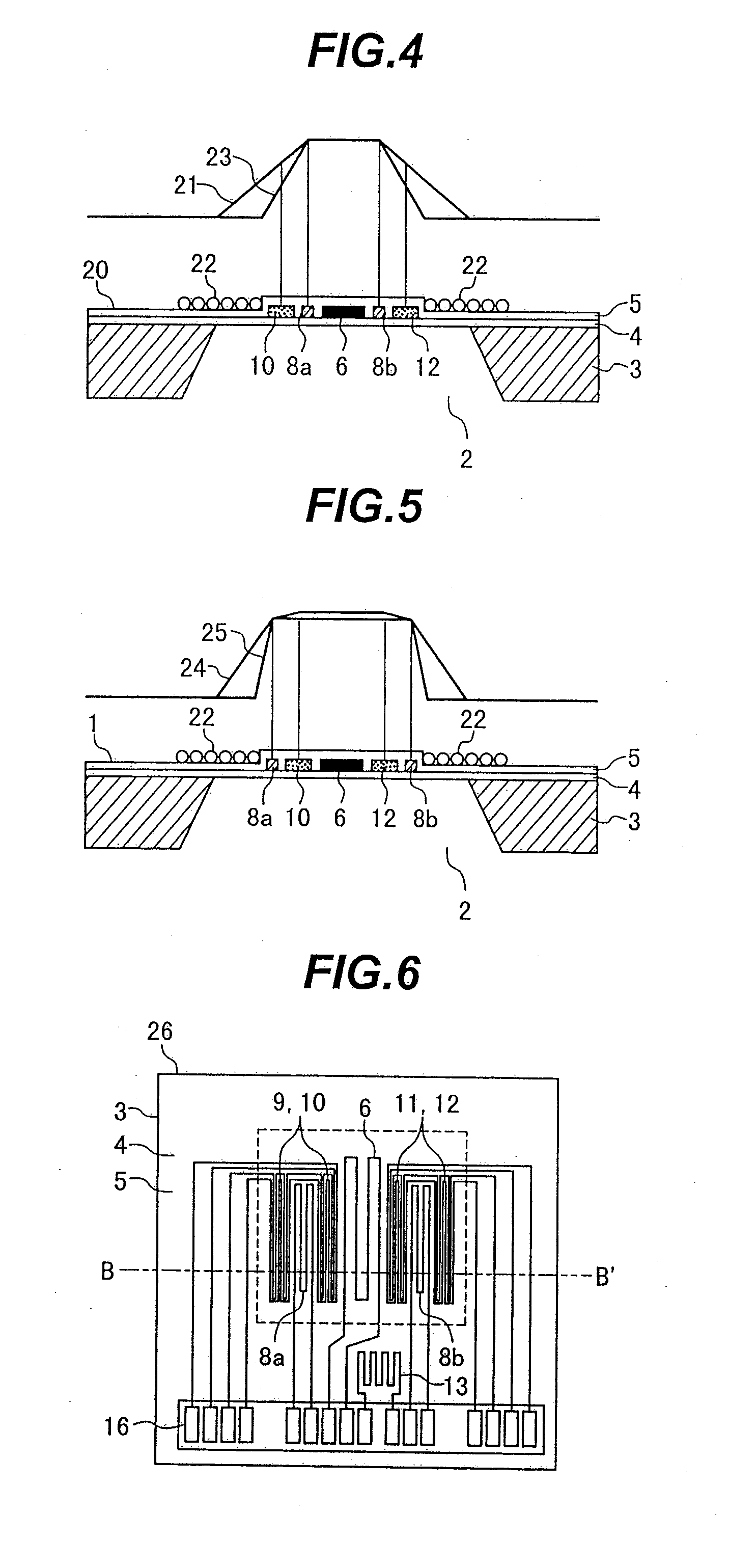
[0064]FIG. 6 is a plan view of a sensor device 26 in the second embodiment of the present invention. FIG. 7 depicts a cross-section along the line B-B′ in FIG. 6.
[0065]What differentiates the thermal flowmeter according to the second embodiment of the present invention from that of the first embodiment is the arrangement of the heating temperature sensors 8a and 8b and temperature difference sensors 9, 10, 11 and 12. The drive / detect method for and with the sensor device 26 is the same as in the first embodiment. The following describes what is different from the first embodiment.
[0066]In FIG. 6 and FIG. 7, the temperature difference sensors 9 and 10 are patterned upstream of the heater resistor 6 so that they are disposed respectively upstream and downstream of the upstream heating temperature sensor 8a. That is, the upstream heating temperature sensor 8a is sandwiched between the upstream temperature difference sensors 9 and 10.
[...
third embodiment
[0070]The following describes the present invention.
[0071]FIG. 8 depicts a cross-section of the diaphragm of a sensor device 27 in the third embodiment of the present invention. What differentiates the thermal flowmeter according to the third embodiment of the present invention from that of the second embodiment is the arrangement of the heating temperature sensors 8a and 8b and temperature difference sensors 9, 10, 11 and 12 in the sensor device 26. The drive / detect method for and with the sensor device is the same as in the first embodiment. The following describes what is different from the first embodiment.
[0072]Viewed from the top of the sensor device 27 shown in FIG. 8, the heating temperature sensors 8a and 8b are disposed on the temperature difference sensors 9, 10, 11 and 12 via the insulation film 5. That is, viewed from the top of the sensor device 27, the upstream heating temperature sensor 8a overlaps with the upstream temperature difference sensors 9 and 10 while the d...
PUM
 Abstract
Description
Claims
Application Information
 - R&D
- Intellectual Property
- Life Sciences
- Materials
- Tech Scout
- Unparalleled Data Quality
- Higher Quality Content
- 60% Fewer Hallucinations
Browse by: Latest US Patents, China's latest patents, Technical Efficacy Thesaurus, Application Domain, Technology Topic, Popular Technical Reports.
© 2025 PatSnap. All rights reserved.Legal|Privacy policy|Modern Slavery Act Transparency Statement|Sitemap|About US| Contact US: help@patsnap.com


