Cam shaft phase setter and vacuum pump for an internal combustion engine

a technology of cam shaft and vacuum pump, which is applied in the direction of mechanical equipment, valve details, braking systems, etc., can solve the problems of limiting the torque level and the arrangement of vacuum pump, and the partial vacuum of the suction pipe which arises during operation is insufficient to power the brake servo, so as to save space and weight, and the effect of easy mounting

Active Publication Date: 2008-11-20
SCHWABISCHE HUTTENWERKE AUTOMOTIVE CMBH
View PDF12 Cites 34 Cited by
  • Summary
  • Abstract
  • Description
  • Claims
  • Application Information

AI Technical Summary

Benefits of technology

[0008]It is an object of the invention to arrange a cam shaft phase setter and a vacuum pump for an internal combustion engine in such a way as to save space and weight and such that they can be easily mounted.
[0012]The phase setter and vacuum pump are combined by means of the attachment housing to form one functional unit. To the extent to which the attachment housing of the vacuum pump takes on functions for the phase setter, the internal combustion engine itself is relieved of the functions in question. A structural part of the attachment housing which is required for the vacuum pump can also for example simultaneously form a structural part for the phase setter. This helps to reduce the weight and required installation space of the phase setter and vacuum pump, and to reduce the number of parts which are to be mounted in connection with the phase setter and the vacuum pump. This also simplifies the interface between the internal combustion engine on the one hand and the phase setter and vacuum pump on the other. The number of interfaces can be reduced, for example by driving the vacuum pump via the phase setter, such that it does not therefore have to be additionally connected to a drive.
[0020]The attachment housing can advantageously serve to rotary-mount a gear wheel, accommodate such a gear wheel, or accommodate or support another gear member, for example a toothed belt, a simple belt or a chain. The gear member which is rotatably mounted or otherwise supported or accommodated can in particular be an output wheel onto the vacuum pump or, as applicable, an output wheel from the vacuum pump onto the phase setter, an output wheel onto another cam shaft of the internal combustion engine or an output wheel for the rotary drive of the first rotor. It is also possible to drive the other cam shaft and to output from this cam shaft onto the first rotor of the phase setter. The more gear members, required for driving onto or outputting from the phase setter, are rotatably mounted or otherwise supported or accommodated by the attachment housing, i.e. mounted on or in the attachment housing, the simpler the configuration for integrating the phase setter and vacuum pump on the internal combustion engine.
[0021]In preferred embodiments, the vacuum pump is driven via, i.e. from the phase setter. If, as is preferred, the vacuum pump is a rotational pump comprising at least one rotatable conveying member, then one of the rotors can be connected, secured against rotating, to the conveying member. If they are arranged coaxially next to each other on the same rotational axis, then instead of being connected, rotationally fixed, one of the rotors of the phase setter can be mechanically coupled to the conveying member of the pump via a gear system, for example by means of a planetary gear system. External-axle gear systems are preferred. When coupled by means of an external-axle gear system, the rotational axes of the phase setter and the rotational axis of the vacuum pump, which is preferably formed as a rotational pump, differ. In this case, the rotational axes are expediently parallel to each other. External-axle spur wheel gear systems are preferred gear systems. In principle, however, the gear system can also be formed with an internal axle or by means of a traction means such as for example a toothed belt. By means of a gear system, the rotational speed of the rotor or stator can advantageously be geared up to a higher rotational speed of the conveying member. By gearing up the rotational speed of the rotor which outputs onto the pump, the pump can be realised with a smaller volume and a correspondingly smaller required installation space for the same conveying output. By gearing down the rotational speed, the frictional output and consequently the wear can be reduced.

Problems solved by technology

In diesel engines and also modern spark-ignition engines with fuel injection, the suction pipe partial vacuums which arise during operation are in many cases not sufficient for powering the brake servos, because the load control deviates from conventional spark-ignition engines.
A direct coupling between the vacuum pump and a cam shaft also restricts the torque level and the arrangement of the vacuum pump.

Method used


Image

  • Cam shaft phase setter and vacuum pump for an internal combustion engine
  • Cam shaft phase setter and vacuum pump for an internal combustion engine
  • Cam shaft phase setter and vacuum pump for an internal combustion engine

Examples


Embodiment Construction

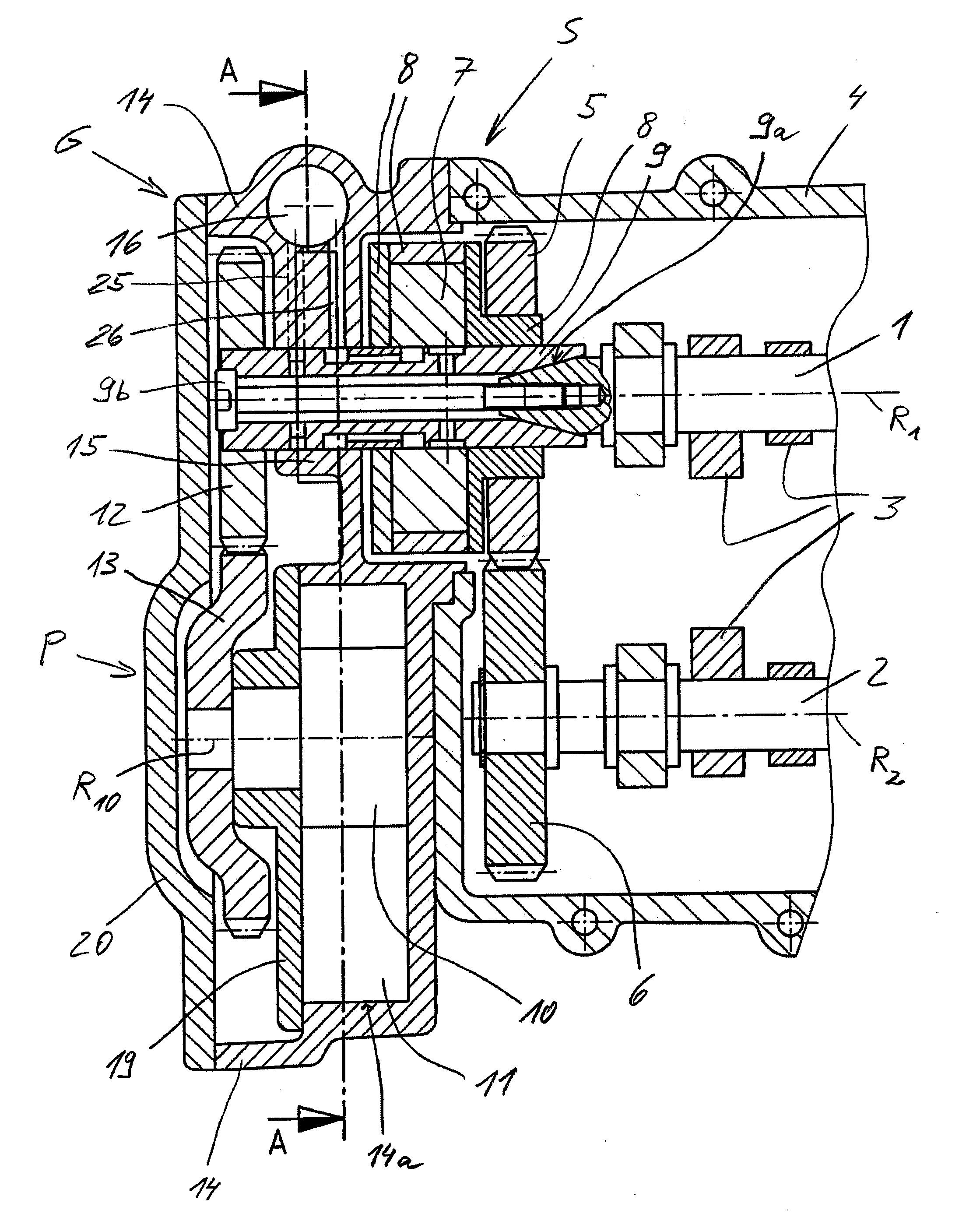
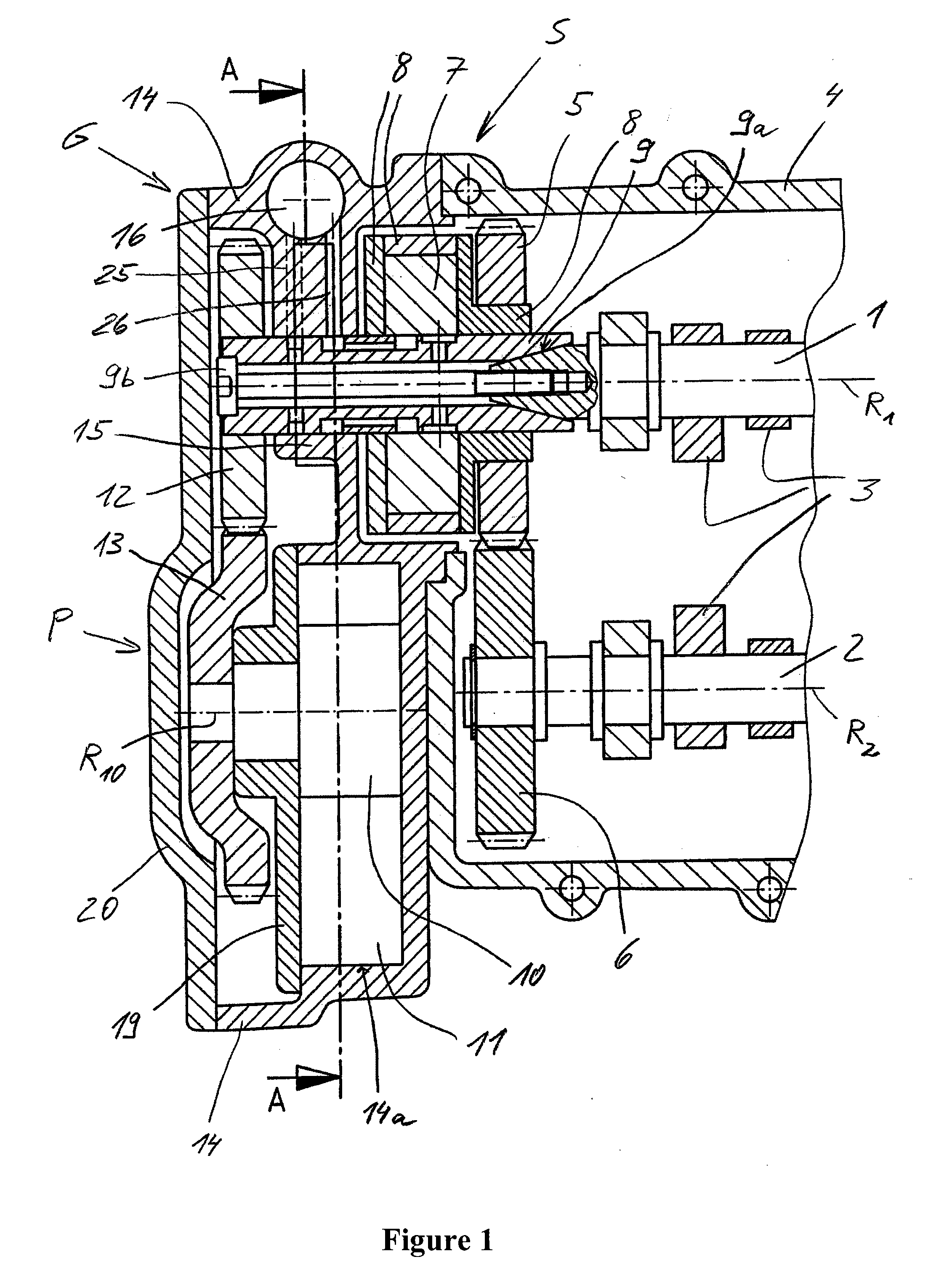
[0042]FIG. 1 shows a phase setter S and a vacuum pump P which are arranged on an internal combustion engine by means of a common attachment housing G. The internal combustion engine comprises two cam shafts 1 and 2 which are arranged next to each other and comprise cams 3, one of which serves to control inlet valves and the other of which serves to control outlet valves of the internal combustion engine. The cam shafts 1 and 2 are arranged in an engine housing 4—in the example embodiment, a cylinder head—of the internal combustion engine, such that they can rotate about their respective rotational axes R1 and R2. The cam shaft 1 is driven by a crankshaft of the internal combustion engine, for example via a drive wheel arranged at an end (not shown) of the cam shaft 1 facing away from the phase setter S.

[0043]The phase setter S comprises a gear wheel 5, via which it drives the cam shaft 2. The gear wheel 5 is an externally toothed spur wheel. It is in toothed engagement with another ...


PUM


Abstract

A device for adjusting the phase position of a cam shaft of an internal combustion engine and for supplying an assembly with a partial vacuum, said device comprising: a phase setter for adjusting the phase position of the cam shaft relative to a crankshaft of the internal combustion engine; a vacuum pump for the assembly; and an attachment housing for the vacuum pump, wherein the attachment housing is mounted on the internal combustion engine and forms a housing or at least a housing cover for the phase setter.

Description

[0001]This application claims priority to German Utility Registration. No. 10 2007 020 431.2 filed Apr. 27, 2007, which is incorporated in its entirety by reference herein.BACKGROUND OF THE INVENTION[0002]1. Technical Field[0003]The invention relates to a device comprising a cam shaft phase setter and a vacuum pump for mounting on an internal combustion engine, and also to an internal combustion engine with the device mounted.[0004]2. Description of the Related Art[0005]In order to reduce brake pedal forces in motor vehicles, in particular passenger cars and light-duty commercial vehicles, the vehicles are equipped with pneumatic brake servos. In conventional passenger car spark-ignition engines, the partial vacuums required for brake servos are applied by the suction pipe partial vacuums acting behind the suction inlet system throttle valve. In diesel engines and also modern spark-ignition engines with fuel injection, the suction pipe partial vacuums which arise during operation ar...

Claims


Application Information

Patent Timeline
Patent Type & Authority Applications(United States)
IPC IPC(8): F01L1/34F02B67/04F02B63/06
CPCB60T13/52B60T17/02F01L1/34F01L1/3442F01L2001/028F01L2001/0537F01L2001/3444F01L2001/34446F01L2001/34496F02B67/04
Inventor BOHNER, JURGENWELTE, CLAUSMAUCHER, FRANZ
Owner SCHWABISCHE HUTTENWERKE AUTOMOTIVE CMBH
Why Eureka
Try Eureka