
Stator coil with improved heat dissipation

a stator coil and heat dissipation technology, which is applied in the direction of instruments, light beam reproducing, transportation and packaging, etc., can solve the problems of reducing the efficiency and durability of the components as well as the equipment as a whole, the insulation only further adds to the complications of dissipating heat, and other difficulties in the prior art. , to achieve the effect of high thermal conductivity, high thermal conductivity and high thermal conductivity

Active Publication Date: 2008-11-20
SIEMENS ENERGY INC
View PDF55 Cites 45 Cited by
  • Summary
  • Abstract
  • Description
  • Claims
  • Application Information

AI Technical Summary

Benefits of technology

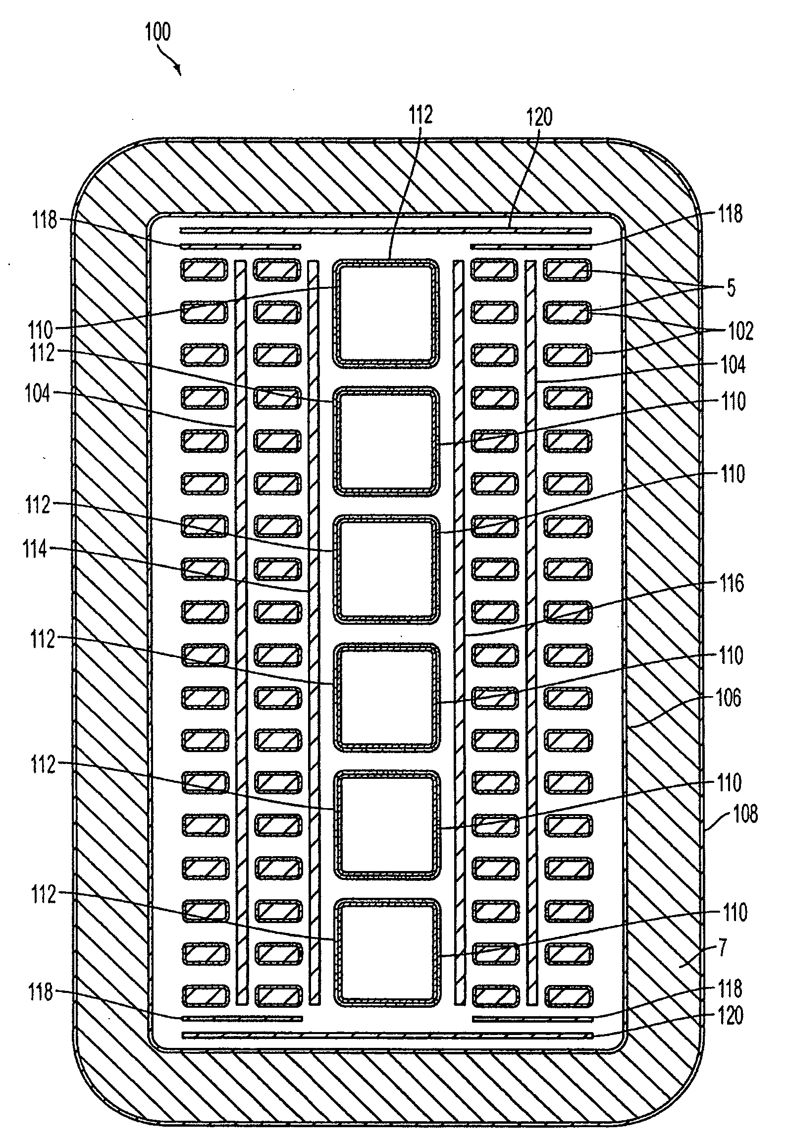
[0009]In accordance with a first aspect of the present invention, a stator coil is provided. The stator coil may comprise a plurality of copper strands and a layer of high thermal conductivity polymer disposed adjacent at least one of the plurality of copper strands. The high thermal conductivity polymer may comprise a host polymer and a high thermal conductivity filler. The high thermal conductivity polymer improves heat transfer.
[0010]In accordance with another aspect of the present invention, a method of improving heat dissipation of a stator coil for use in a generator is provided. The method may comprise providing a high thermal conductivity polymer and a plurality of copper strands. The high thermal conductivity polymer may comprise a host polymer and a high thermal conductivity filler. The method may further comprise providing the high thermal conductivity polymer adjacent at least one of the plurality of copper strands. The high thermal conductivity polymer improves heat transfer.

Problems solved by technology

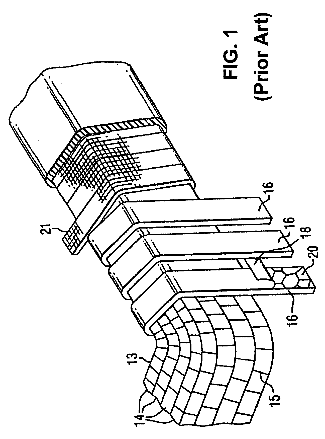
Good electrical insulators, by their very nature, also tend to be good thermal insulators, which is undesirable.
Thermal insulating behavior, particularly for air-cooled electrical equipment and components, reduces the efficiency and durability of the components as well as the equipment as a whole.
Unfortunately this amount of insulation only further adds to the complications of dissipating heat.
Other difficulties with the prior art also exist, some of which will be apparent upon further reading.

Method used


Image

  • Stator coil with improved heat dissipation
  • Stator coil with improved heat dissipation
  • Stator coil with improved heat dissipation

Examples


Embodiment Construction

[0016]In the following detailed description of the preferred embodiments, reference is made to the accompanying drawings that form a part hereof, and in which is shown by way of illustration, and not by way of limitation, specific preferred embodiments in which the invention may be practiced. It is to be understood that other embodiments may be utilized and that changes may be made without departing from the spirit and scope of the present invention.

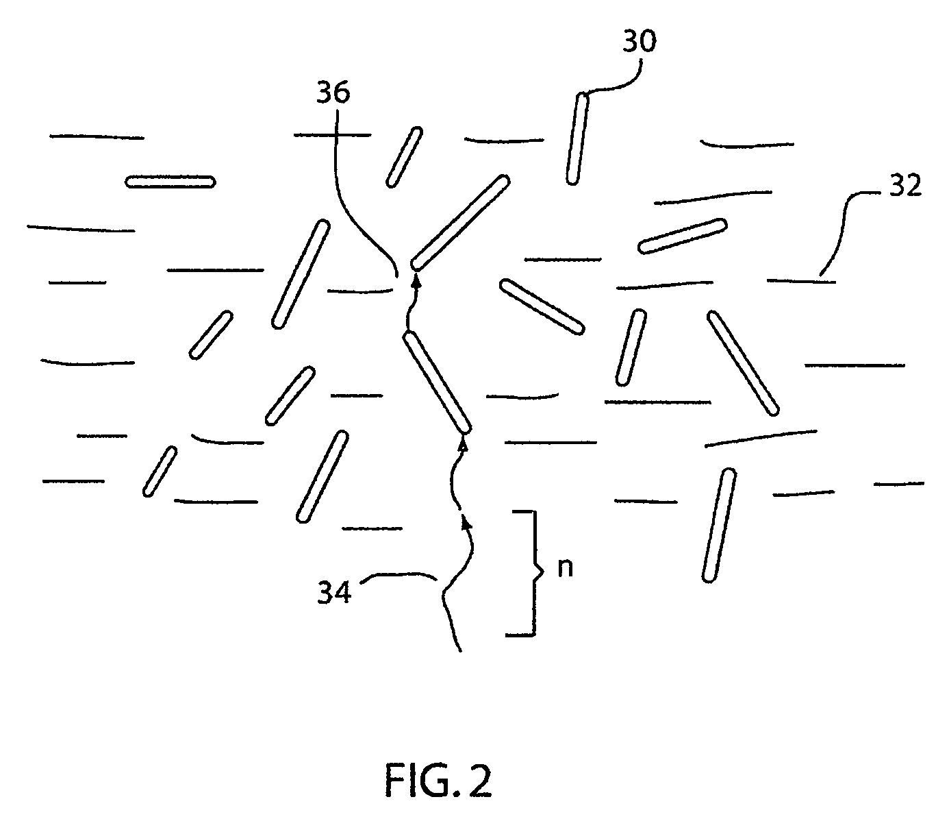
[0017]High thermal conductivity (HTC) composites comprise a resinous host network combined with fillers that are two phase organic-inorganic hybrid materials. The organic-inorganic hybrid materials are formed from two phase organic-inorganic composites, from organic-inorganic continuous phase materials that are based on molecular alloys, and from discrete organic-dendrimer composites in which the organic-inorganic interface is non-discrete with the dendrimer core-shell structure. Phonon transport is enhanced and phonon scattering is redu...


PUM

PropertyMeasurementUnit
Lengthaaaaaaaaaa
Lengthaaaaaaaaaa
Nanoscale particle sizeaaaaaaaaaa

Abstract

A stator coil includes a plurality of copper strands and a layer of high thermal conductivity polymer disposed adjacent at least one of the copper strands. The high thermal conductivity polymer includes a host polymer and a high thermal conductivity filler. The high thermal conductivity polymer improves heat transfer from the plurality copper strands.

Description

CROSS-REFERENCE TO RELATED APPLICATIONS[0001]This application is a continuation-in-part of U.S. application Ser. No. 11 / 152,983, entitled High Thermal Conductivity Materials Incorporated Into Resins, filed Jun. 14, 2005, which claims the benefit of U.S. Provisional Application No. 60 / 580,023, filed Jun. 15, 2004, and is related to U.S. application Ser. No. 11 / 152,984, entitled Structured Resin Systems With High Thermal Conductivity Fillers, filed Jun. 14, 2005, all of which are hereby incorporated herein by reference.FIELD OF THE INVENTION[0002]The present invention relates to a method and structure for improving heat dissipation in a generator stator coil by using an electrical insulation having a high thermal conductivity, and more particularly, a method and structure for using an electrical insulation having high thermal conductivity fillers included in a host polymer to improve heat transfer from the stator coil.BACKGROUND OF THE INVENTION[0003]With the use of any form of electr...

Claims


Application Information

Patent Timeline
IPC IPC(8): H02K9/22
CPCC08J5/10C08K3/14C08K3/22D21H13/44H02K3/24Y10T428/26H02K3/345Y10S174/20Y10T428/25Y10T428/254H02K3/30
Inventor NELSON, THOMAS I.WOOD, JOHN W.MONTGOMERY, LON W.
Owner SIEMENS ENERGY INC
Learn More