Method and apparatus of a ring oscillator for phase locked loop (PLL)

a phase lock and oscillator technology, applied in the direction of oscillator generators, pulse generation by logic circuits, pulse techniques, etc., can solve the problems of high noise resistance of pll output clocks, output clocks of plls jittering from their ideal timing, and bandwidth usually remains good

Inactive Publication Date: 2008-11-20
TEXAS INSTR INC
View PDF9 Cites 44 Cited by
  • Summary
  • Abstract
  • Description
  • Claims
  • Application Information

AI Technical Summary

Problems solved by technology

However, an increasingly noisy environment of the PLL has created a high demand for noise resistive PLL architectures.
The noise is typically in the form of supply and substrate noise causing the output clocks of a PLL to jitter from their ideal timing.
However, due to process technology factors and stability requirements the loop bandwidth usually remains well below the lowest operating frequency.
However, the biasing circuits used to adjust the PLL inject additional noise into the PLL.

Method used


Image

  • Method and apparatus of a ring oscillator for phase locked loop (PLL)
  • Method and apparatus of a ring oscillator for phase locked loop (PLL)
  • Method and apparatus of a ring oscillator for phase locked loop (PLL)

Examples


Embodiment Construction

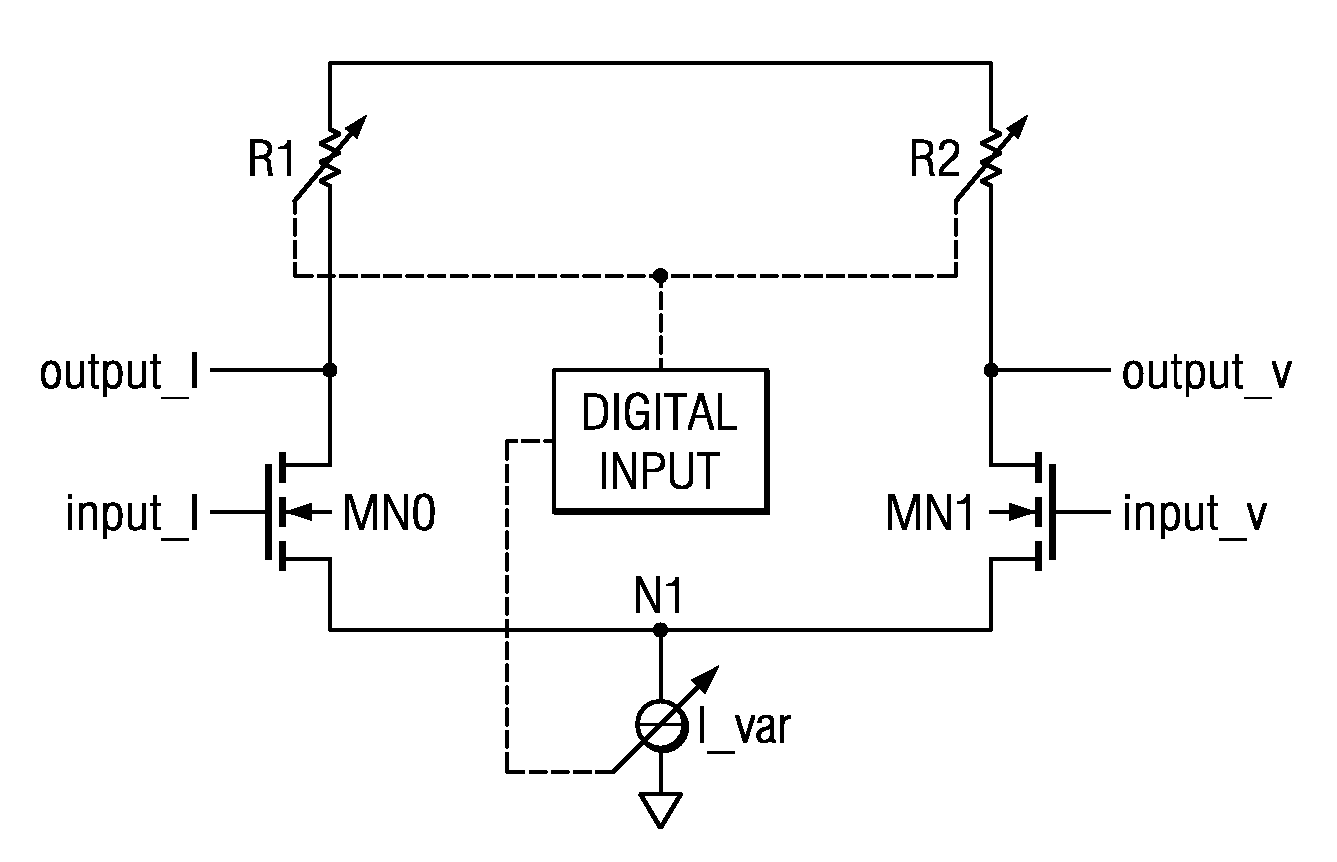
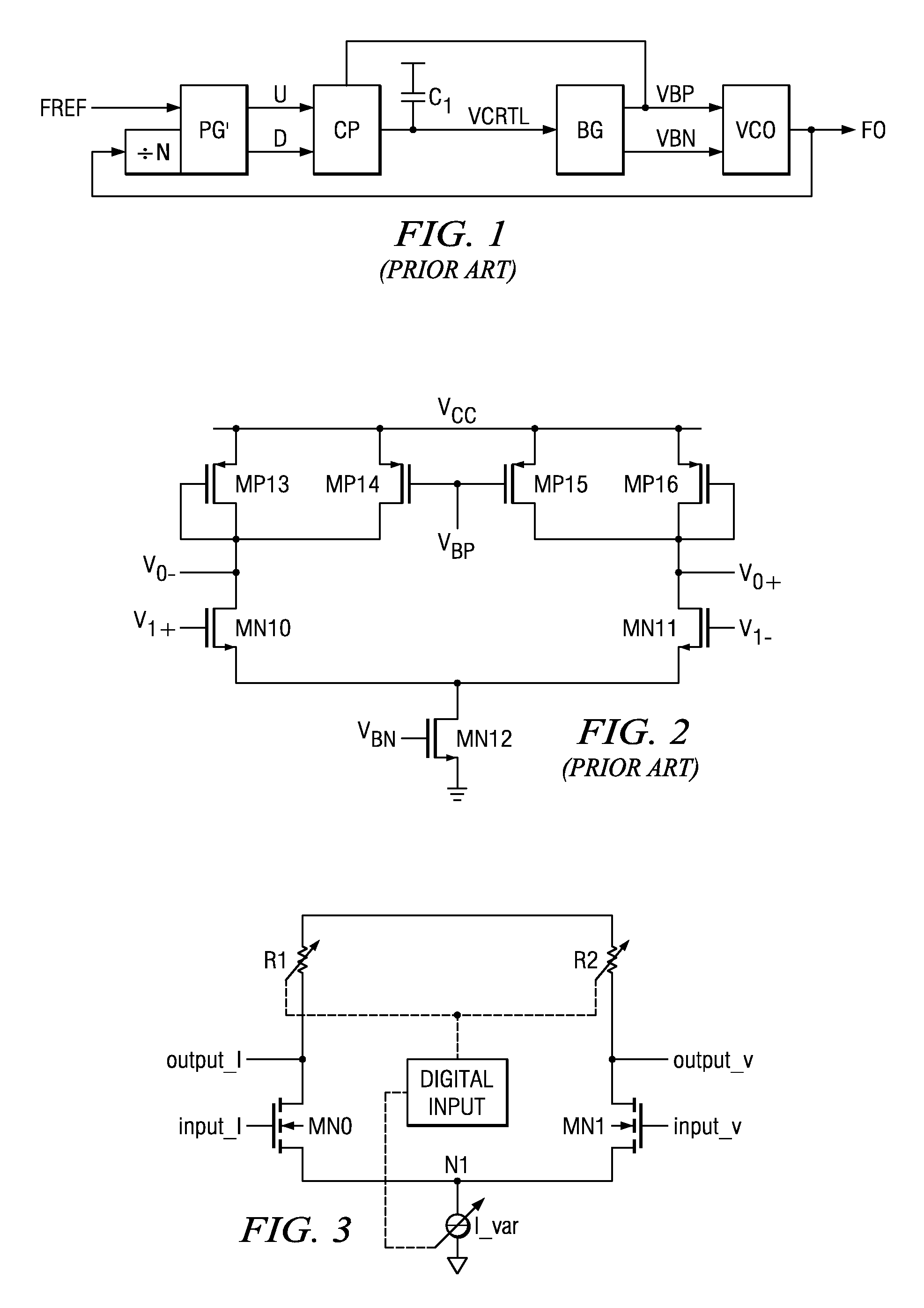
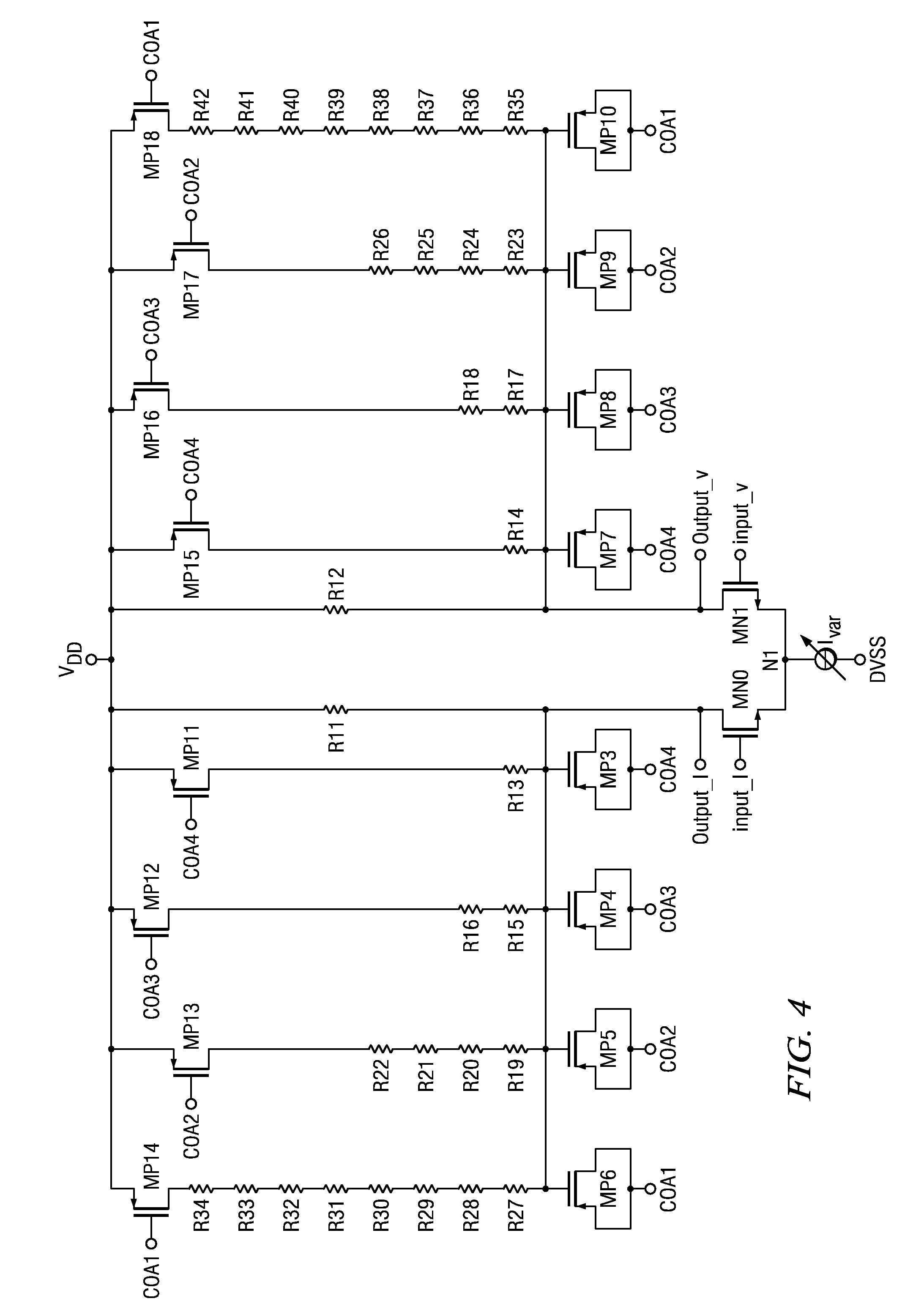
[0016]In one embodiment, a ring oscillator with a plurality of cascaded inverting delay stages is provided. Each delay stage includes a differential pair of input transistors, a variable resistive load coupled to each transistor, a differential output between the variable resistive load and the corresponding input transistor, a variable current source coupled to the differential pair of transistors for variably setting a bias current through the differential pair of transistors, and an input coupled to the variable resistive load and the variable current source for receiving an configuration signal, wherein the variable resistive load and the variable current source are changed in response to the configuration signal, such that the bias current increases, while the variable resistive load decreases and vice versa.

[0017]The ring oscillator may be adjusted in a feed forward manner in order to match the specific operating requirements. Using a variable resistive load allows a greater o...


PUM


Abstract

The present invention relates to a ring oscillator including a delay stage, the delay stage includes a differential pair of input transistor, a variable resistive load coupled to the transistor, a differential output between the variable resistive load and the corresponding input transistor, a variable current source coupled to the differential pair of transistors for variably setting a bias current through the differential pair of transistors, and an input coupled to the variable resistive load and the variable current source for receiving an configuration signal, wherein the variable resistive load and the variable current source are changed in response to the configuration signal, wherein the bias current of the variable current source increases and the variable resistive load decreases, and vice versa.

Description

CROSS-REFERENCE TO RELATED APPLICATIONS[0001]The present invention claims benefit of German patent application filing number 10 2007 023 044.5, filed on May 16, 2007, which is herein incorporated by reference, and U.S. Provisional Application Ser. No. 61 / 016,685, filed on Dec. 26, 2007, which is also herein incorporated by reference.BACKGROUND OF THE INVENTION[0002]1. Field of the invention[0003]The present invention generally relates to a phase locked loop (PLL), more particularly, to a controllable ring oscillator with low phase noise.[0004]2. Description of the Related Art[0005]High frequency integrated circuits based on CMOS technology, the use of which is widespread in today's electronic devices, require all kinds of clock generation circuits to handle clock distribution and clock synchronization. Synchronization is provided by on-chip oscillators locked by phase locked loop (PLL) or delay locked loop (DLL) circuits, which are generally well known in the art.[0006]A PLL include...

Claims


Application Information

Patent Timeline
Patent Type & Authority Applications(United States)
IPC IPC(8): H03K3/03H03K5/00
CPCH03K5/133H03K2005/00058H03K2005/00208
Inventor REFELD, THOMASVANSELOW, FRANK
Owner TEXAS INSTR INC
Why Eureka
Try Eureka