High back EMF, high pressure subwoofer having small volume cabinet, low frequency cutoff and pressure resistant surround

a subwoofer and high-back emf technology, applied in the direction of transducer casings/cabinets/supports, stereophonic arrangments, electrical transducers, etc., can solve the problems of low frequency, difficult design of cones of that size, and difficulty in many full-range loudspeakers to reprodu

Inactive Publication Date: 2005-02-17
CARVER ROBERT W
View PDF0 Cites 33 Cited by
  • Summary
  • Abstract
  • Description
  • Claims
  • Application Information

AI Technical Summary

Benefits of technology

As a result of the foregoing, a subwoofer embodying features of the present invention is characterized by its extremely small size, high efficiency, high power and high acoustically accurate sound levels, all without requiring large, heavy and costly heat sinks and / or storage capacitors.
It is a further object of the invention to provide a system for maintaining tinsel leads under tension during peak-to-peak reciprocation of the subwoofers' voice coil driven components so as to prevent undesired noise resulting from slapping of the tinsel leads against the speaker cone in the voice coil driven woofer.

Problems solved by technology

These low frequencies are difficult for many full range loudspeakers to reproduce because the bass drivers for full range loudspeakers must handle a wider frequency range—i.e., their frequency response must extend much higher in the audible frequency range, often to about 2,500 Hz or even higher depending upon the design of the loudspeaker.
One disadvantage of having a driver with a fifteen inch cone is that it is difficult to design a cone of that size which is rigid enough to resist distortion when the cone has such a large surface area.
However, such a subwoofer suffers from the disadvantage that four drivers are required; and, this greatly increases the size of the cabinet required, cost and weight.
However, when the stroke of the driver is increased, the efficiency of the driver is substantially reduced, as less of the voice coil will remain in the magnetic gap.
Prior art subwoofer systems invariably require a large cabinet.
However, large cabinets are necessary for prior art subwoofers for reasons having nothing to do with the number of drivers installed therein.
Atmospheric pressures outside the cabinet also affect these forces.
If the stroke of the driver is short, the driver cone will have physical limitations on how far it can enter into the cabinet and how far it can extend outwardly from the cabinet.
However, power amplifiers capable of providing such power levels tend to create large amounts of heat which, in turn, requires large heat sinks, massive power reserve capacitors, and large transformers, all of which are large in size, heavy, and expensive.
All of these factors are undesirable; and, all tend to reinforce the need for a relatively large cabinet.
Thus, as can be seen from the foregoing, because of the large power demands required by subwoofer systems and the large cost involved in providing large amounts of power amplification, prior art subwoofer apparatus have invariably required, and utilized, large cabinets which held drivers having large diameters and short strokes.
However, normal listening environments often do not have space for such a large cabinet.
Unfortunately, if one wishes to reduce the low frequency cutoff (f0) from, for example, 50 Hz to 18 Hz while retaining the same efficiency, the volume of the woofer cabinet must be significantly increased.
That, of course, would be ludicrous and is neither practical, cost effective nor economically feasible from a commercial standpoint.
Conversely, if the designer wishes the box to be small, there has heretofore been no way to get a lot of bass out of it, either low or loud, with high efficiency.
Consequently, the voice coil will soon overheat; and, in fact, that has been a major stumbling block to the development of very small, but powerful, subwoofers.
Unfortunately, however, when such a subwoofer driver is built and installed in a box—any box—bass output is found to be actually far less than before the magnetic field was increased!
Unfortunately, subwoofers designed with magnets optimized for maximum bass output are very inefficient.
Another major problem encountered by subwoofer designers is directly related to the fact that subwoofers are exceptionally prone to hum problems induced by power line “ground loops”.
This constitutes a loop called a “ground loop”, and it generates a very undesirable 60 Hz hum.
This is because while they effectively “break” the ground(s), they do not suppress the hum voltage generated across the broken ground or grounds.

Method used


Image

  • High back EMF, high pressure subwoofer having small volume cabinet, low frequency cutoff and pressure resistant surround
  • High back EMF, high pressure subwoofer having small volume cabinet, low frequency cutoff and pressure resistant surround
  • High back EMF, high pressure subwoofer having small volume cabinet, low frequency cutoff and pressure resistant surround

Examples


Embodiment Construction

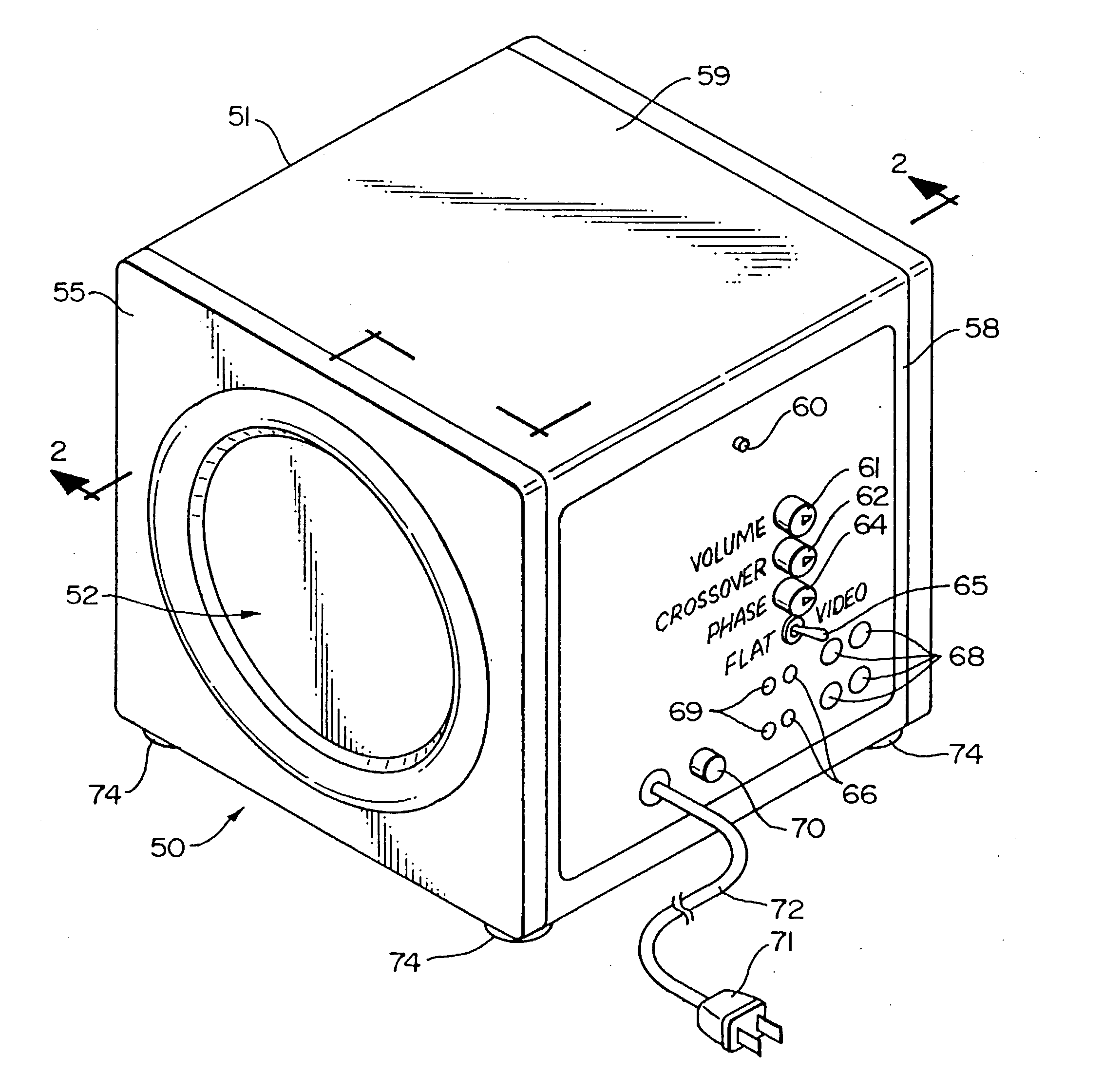
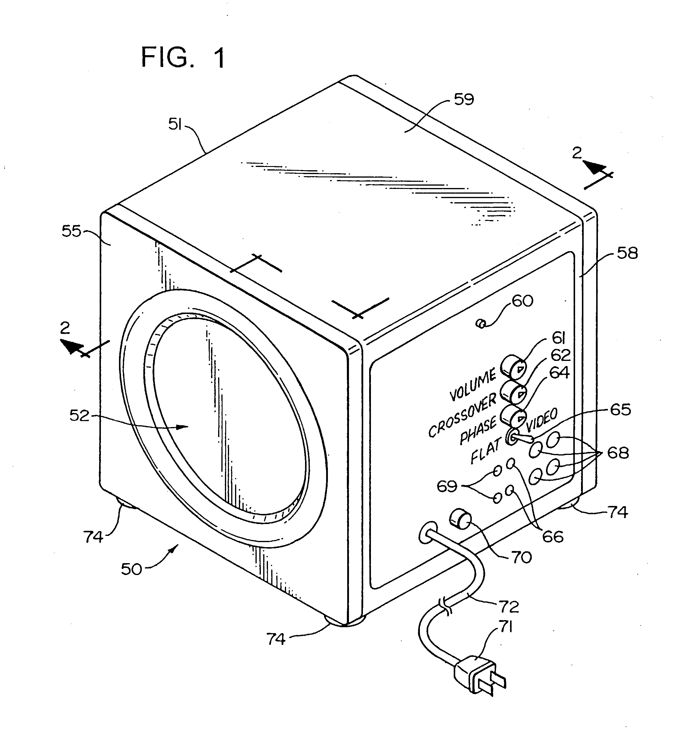
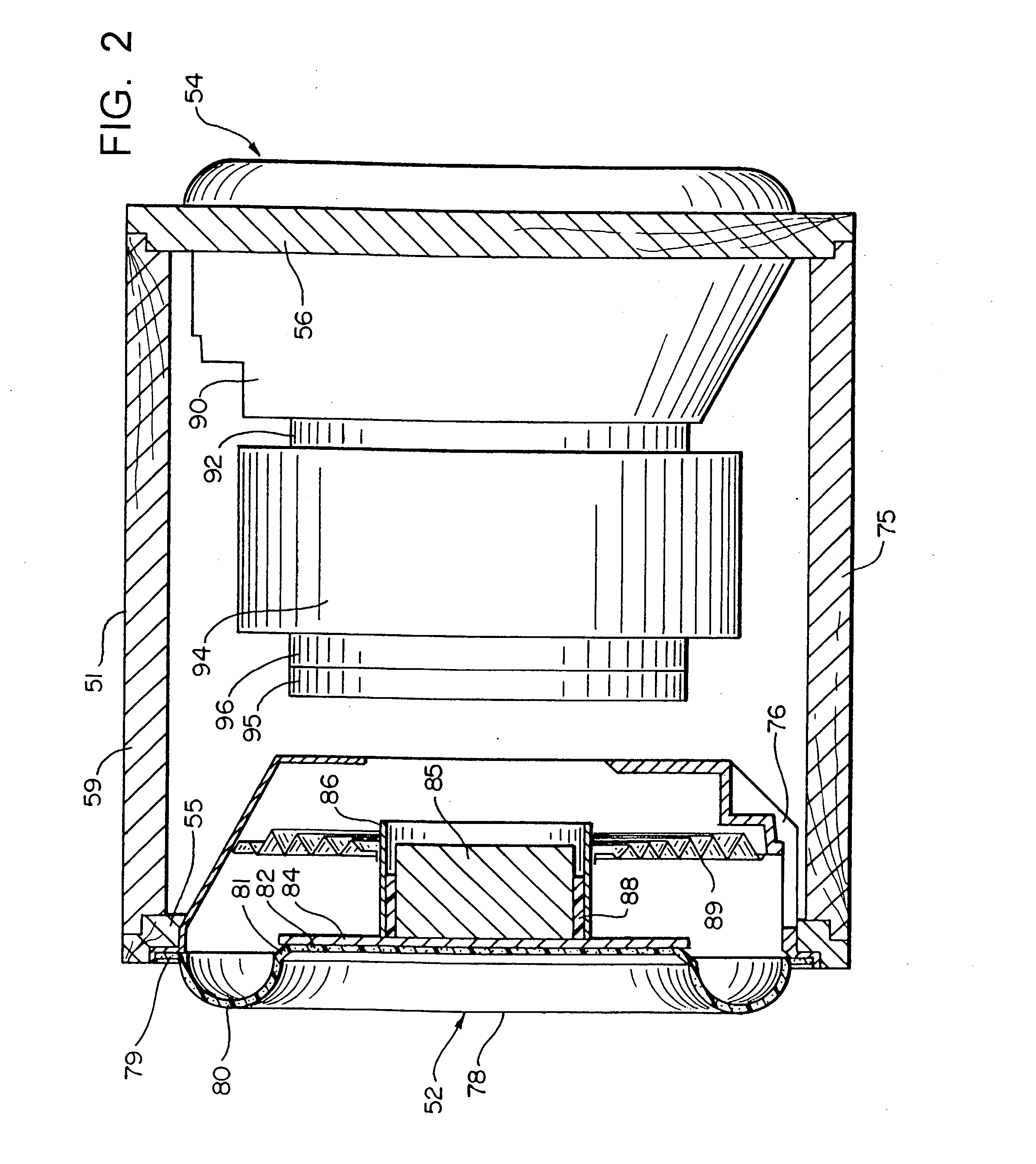
Turning now to the drawings, exemplary embodiments of the present invention will now be described. Thus, referring first to FIG. 1, an exemplary subwoofer, generally indicated at 50, embodying features of the present invention has been depicted. As here shown, the subwoofer 50 includes a cabinet 51 which encloses two drivers, generally indicated at 52 and 54 (only driver 52 is visible in FIG. 1; and, the details of the two exemplary drivers 52, 54 are more specifically shown in FIGS. 2, 3 and 5), which are each oriented in a PUSH / PULL configuration on opposite sides of the cabinet 51. That is, the visible driver 52 depicted in FIG. 1 comprises a mass driven driver shown in greater detail in FIG. 2 and is mounted in one wall of the cabinet (here the left sidewall 55 of the cabinet 51 as viewed in FIG. 1) and fires in PUSH / PULL directions; while the second driver 54 (not visible in FIG. 1, but shown in elevation in FIG. 2 and in section in FIG. 3) is mounted in the opposite or right ...


PUM

PropertyMeasurementUnit
volumeaaaaaaaaaa
frequencyaaaaaaaaaa
frequencyaaaaaaaaaa

Abstract

A subwoofer cabinet having a volume less that 1 ft3 axially aligned openings in opposed cabinet walls; first and second cages mounted on respective ones of the walls in alignment with the openings; a voice coil driven driver including an annular 225 oz. magnet affixed to the first cage; a stationary pole piece extending through the magnet and defining a magnetic gap therebetween; a voice coil mounted on a cylindrical voice coil former positioned within the gap; a cone affixed to one end of the former; a first flexible surround secured to the outer end of the cone and attached at its periphery to the first cage; a flexible spider secured to the former and at its outer periphery to the first cage; a mass driven driver including a 1.7 lb. mass; a second flexible surround secured to the mass and to the second cage; a flexible spider attached to the second cage and to the mass; both surrounds having a uniform thickness of at least 0.1″, an edgeroll having a diameter of at least 1.5″, and capable of standing off internal pressures of 1.5 lbs. / in2 to 3 lbs. / in2; a drive amplifier capable of delivering 2,700 watts to a nominal 4 ohm resistive load and swinging 104 volts for delivering (+)-v and (−)-v drive signals to the voice coil for driving the voice coil driven driver through a peak-to-peak stroke of about 2.5″ while generating a large back emf sufficient to counter the applied emf and minimize current flow in the voice coil.

Description

BACKGROUND OF THE INVENTION 1. Field of the Invention The present invention relates generally to the field of high fidelity audio reproduction; and, more particularly, concerns subwoofer loudspeaker systems that produce high quality, low distortion and low-frequency sound. 2. Prior Art In the field of high fidelity sound reproduction, a high quality audio system is normally comprised of: a) a signal source, which is generally music or soundtracks from: i) films; ii) compact disk players; iii) laser disk players, and the like; b) a “preamplifier” which receives signals from the signal source and provides an audio signal to a power amplifier which amplifies the signal; and c), loudspeakers that can reproduce the sound from the signal source. Generally, loudspeakers are single enclosures designed to produce most of the audible frequency range, which is from. 20 Hertz (“Hz”) to 20,000 Hz. Modern recording technologies have allowed music and film Producers to make recordings having ...

Claims


Application Information

Patent Timeline
Patent Type & Authority Applications(United States)
IPC IPC(8): H03F1/02H04R1/02H04R1/22H04R1/28H04R3/00
CPCH03F1/0227H03F1/0238H04R1/021Y10T29/49005H04R1/2803H04R1/2834H04R3/00H04R1/227
Inventor CARVER, ROBERT W.
Owner CARVER ROBERT W
Why Eureka
Try Eureka