Bolometric detector, device for detecting submillimetric and millimetric electromagnetic waves that uses such a detector

a detector and detector technology, applied in the direction of photometry, instruments, radiating element structural forms, etc., can solve the problems of significant adverse effect on performance, limitation of actual construction, and insufficient thermal isolation

Inactive Publication Date: 2006-10-19
COMMISSARIAT A LENERGIE ATOMIQUE ET AUX ENERGIES ALTERNATIVES
View PDF5 Cites 33 Cited by
  • Summary
  • Abstract
  • Description
  • Claims
  • Application Information

AI Technical Summary

Problems solved by technology

One of the difficulties that has to be overcome with such detection devices is the limitation imposed by their actual construction because of the proportionality of thermal conductivity and electric conductivity in any conductive material which takes a simple form in the case of metals: Wiedemann Franz's law.
Thus, the electrical link between the antenna and the thermometer is necessarily accompanied by a thermal link which has a significantly adverse effect on the performance of bolometers since they measure a variation in temperature relative to a reference value.
Given this assumption, the antenna is therefore virtually thermally grounded; in other words it is not thermally isolated and because of its mechanical and electrical connection to the thermometer, the latter is not satisfactorily thermally isolated.
This coupling nevertheless requires a submicron gap between the antenna and the thermometer and this complicates the technology involved in producing such a detector considerably.
The load resistance of the antenna is then of the order of one kΩ, which is equivalent to a thermal resistance which is still insufficient and therefore limits the performance of the detector.
Moreover, such a high load resistance value is inevitably accompanied by a reduction in the absorption bandwidth which has a drastic impact on a passive detector, because the absorbed power is proportional to the bandwidth.
Summing up, there is therefore no satisfactory technical solution making it possible to achieve complete or virtually complete thermal isolation of the thermometer or bolometer relatively simply in terms of technology.

Method used


Image

  • Bolometric detector, device for detecting submillimetric and millimetric electromagnetic waves that uses such a detector
  • Bolometric detector, device for detecting submillimetric and millimetric electromagnetic waves that uses such a detector
  • Bolometric detector, device for detecting submillimetric and millimetric electromagnetic waves that uses such a detector

Examples


Embodiment Construction

[0053] Numbers that denote the same components have been retained throughout the various Figures.

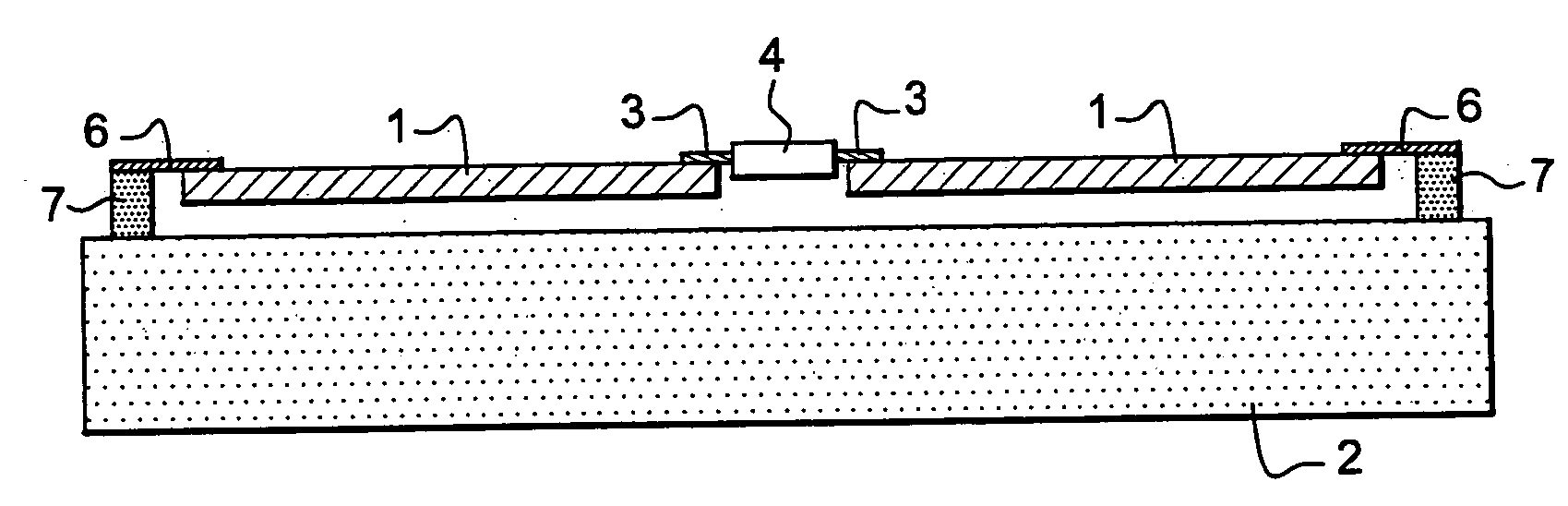
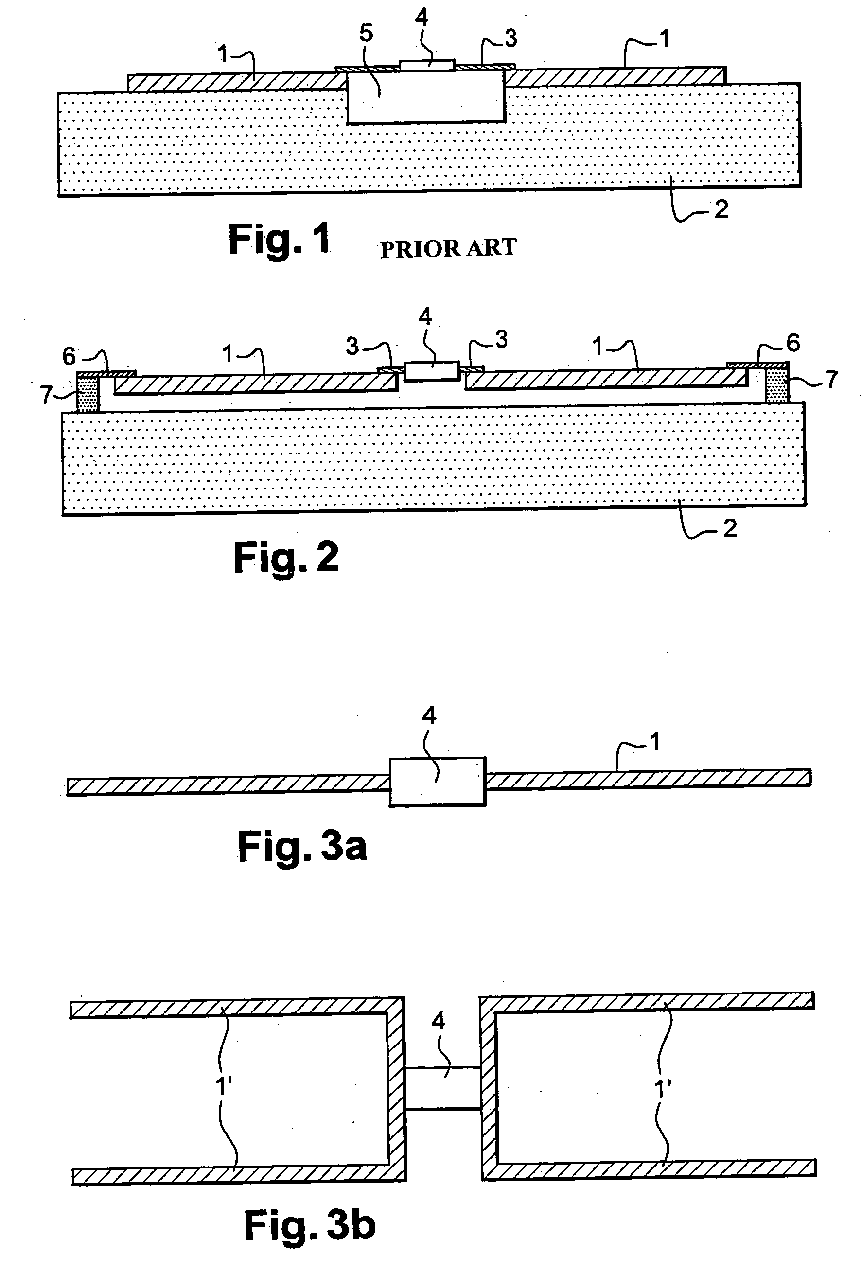
[0054] As is apparent in FIG. 2, the elementary detector according to the invention has an assembly consisting of the receiving antenna (1), the bolometer (4) and a load resistor (3), suspended above substrate (2) by means of isolating arms (6) which rest on posts (7) made for this purpose on said substrate.

[0055] These isolating arms (6) are thermally isolating so that the assembly thus defined is itself thermally isolated from the substrate, this constituting one of the essential objects of the invention.

[0056] In addition, these arms (6) are electrically conductive in order to allow stimuli to be applied to the bolometer (4) and to allow the electric signals generated by the latter to be collected subsequent to the detector being irradiated by electromagnetic radiation in the determined wavelength range.

[0057] The detector described in relation to FIGS. 2 and 3a is equipped with a...


PUM


Abstract

This bolometric detector for electromagnetic radiation comprises:
    • a receiving antenna (1) intended for collecting electromagnetic radiation and thus ensuring electromagnetic coupling; a resistive load capable of converting the electromagnetic power collected into heating capacity;
    • a thermometric element (4) connected to the receiving antenna (1) via the resistive load and thermally isolated from a support substrate (2), capable of accommodating an electronic circuit that includes means of electric excitation (stimuli) and means of pre-processing the electric signals generated by said detector.
The receiving antenna (1) is itself isolated from the support substrate (2).

Description

FIELD OF THE INVENTION [0001] The present invention relates to a bolometric detector and to a device for detecting electromagnetic waves, especially millimetric and submillimetric waves, that uses such a detector. [0002] It also relates to the process for producing this detector. [0003] The detection of millimetric waves and, more especially, submillimetric waves has a certain number of attractions, especially on a scientific and technological level. [0004] In fact, this wavelength domain corresponds to many excitation phenomena in matter (phonons, rotation of molecules, intraband transition, etc.). Consequently, the detection of these waves and their interpretation have many applications, especially in the field of analysing atmospheric pollutants, in biophysics because of the absorption of these waves by liquids and also in telecommunications, radio astronomy, anti-collision radar systems, biomedical imaging, etc. [0005] Two different physical principles are currently used in orde...

Claims


Application Information

Patent Timeline
Patent Type & Authority Applications(United States)
IPC IPC(8): G01J5/10
CPCG01J1/0252G01J5/0837H01Q1/44H01Q1/38G01J5/20
Inventor PEYTAVIT, EMILIENOUVRIER-BUFFET, JEAN-LOUIS
Owner COMMISSARIAT A LENERGIE ATOMIQUE ET AUX ENERGIES ALTERNATIVES
Why Eureka
Try Eureka