Liquid crystal display device, electronic device, and driving methods thereof

a liquid crystal display and electronic device technology, applied in static indicating devices, non-linear optics, instruments, etc., can solve problems such as display defects such as blurring of moving images and the like, display defects will be solved completely, and display defects will be generated. , the effect of high video performan

Inactive Publication Date: 2008-11-20
SEMICON ENERGY LAB CO LTD
View PDF37 Cites 56 Cited by
  • Summary
  • Abstract
  • Description
  • Claims
  • Application Information

AI Technical Summary

Benefits of technology

[0014]In recent years, use of an LED as a backlight is being investigated. If an LED is used as a backlight, switching between the backlight being turned on and the backlight being turned off at high speed becomes possible. Furthermore, use of an LED as a backlight has the advantages of luminance characteristics at low temperature being about equal to luminance characteristics in a steady state, luminance being able to be secured instantaneously by input of source voltage, and high voltage not being needed.
[0017]In view of the aforementioned problems, it is an object of the present invention to provide a driving method by which excellent image quality and high video performance can be obtained as well as liquid crystal display devices and electronic devices with excellent image quality and high video performance.
[0018]In the present invention, a pixel for monitor use is provided in a liquid crystal display device, and luminance of the pixel is detected using a light sensor. Herewith, because changes in luminance of a backlight with changes in the environment and the amount of time it takes for response of the liquid crystal become able to be calculated, control of the backlight in real time using the calculated information can be performed. It is to be noted that the “real time” referred to here does not mean “simultaneous” in the strict sense of the word but allows for slight differences in time that are imperceptible to human beings.
[0030]By the present invention, because control corresponding to changes in the environment (for example, temperature, air pressure, and the like) can be performed, display devices that have excellent image quality and high video performance can be provided. Furthermore, by the present invention, liquid crystal display devices and electronic devices in which excellent image quality and high video performance are exhibited even with major changes in the environment can be provided. That is, excellent image quality and high video performance can be obtained even in display panels on streets that are subject to hostile environments, cellular phones, car electronics, and the like.

Problems solved by technology

However, even if an LED is used as a backlight, it does not necessarily mean that problems related to display will be solved completely.
For this reason, when impulse driving is used, a mismatch between timing of the response of the liquid crystal and timing of when the backlight is turned on may occur.
Consequently, display defects such as blurring of moving images and the like come to be generated.
Moreover, full advantage cannot be taken of the superior response characteristics of an LED.
Consequently, it is difficult to say that desired luminance can be obtained no matter what the conditions are.

Method used


Image

  • Liquid crystal display device, electronic device, and driving methods thereof
  • Liquid crystal display device, electronic device, and driving methods thereof
  • Liquid crystal display device, electronic device, and driving methods thereof

Examples


embodiment mode 1

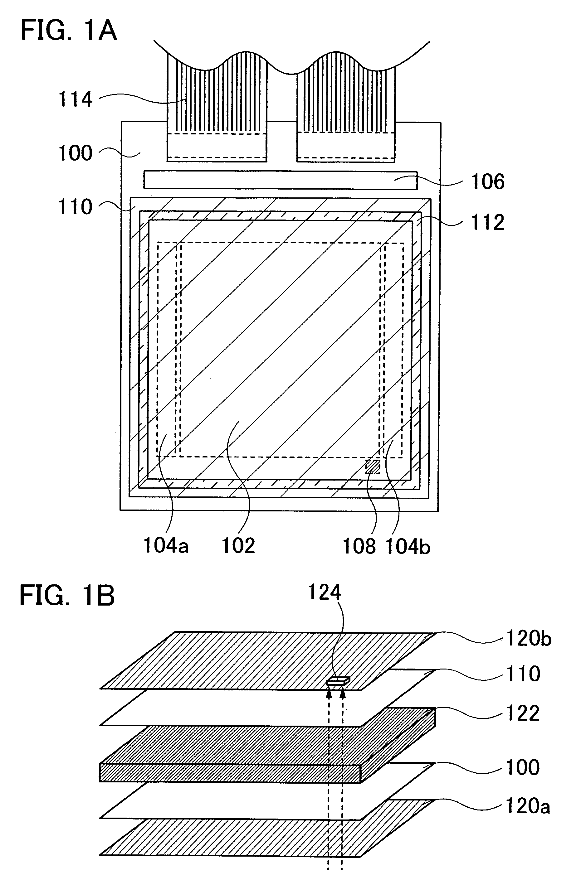
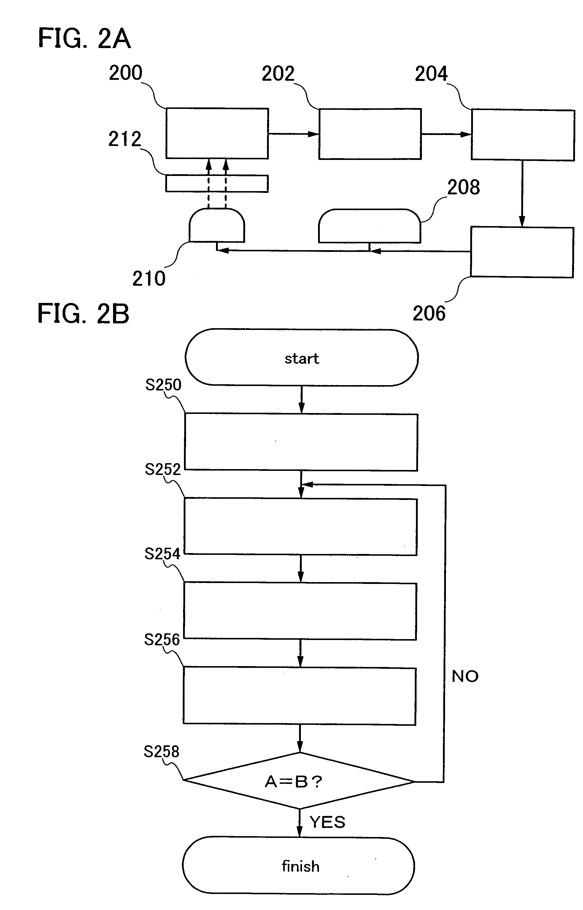
[0062]In the present embodiment mode, an example of a liquid crystal display device and a driving method thereof of the present invention will be described using FIGS. 1A and 1B and FIGS. 2A and 2B.

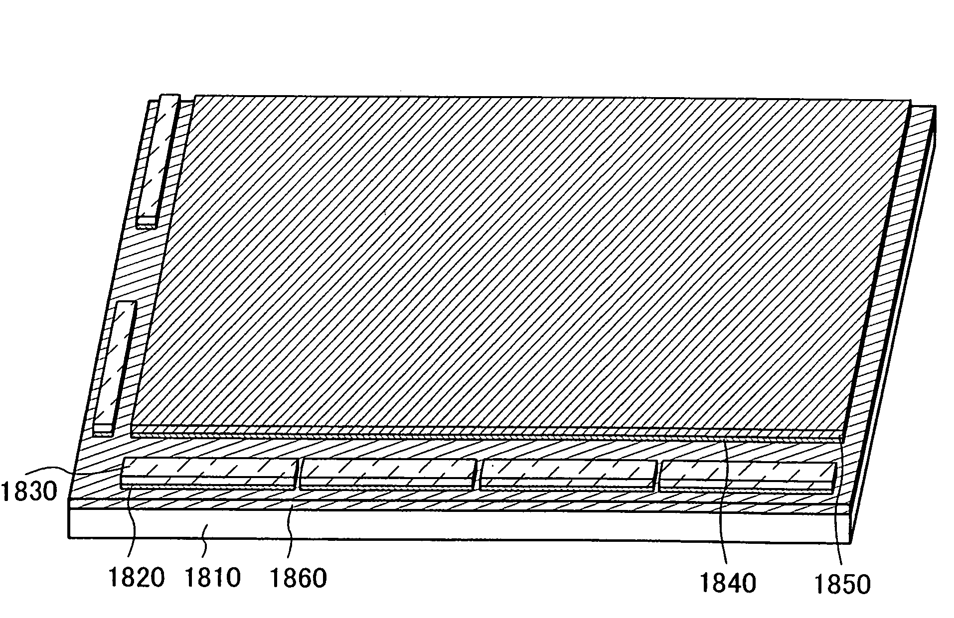
[0063]In FIG. 1A, a planar-view diagram of a panel in which the liquid crystal display device of the present invention can be used is shown. A substrate 100 and a counter substrate 110 are bonded together by a sealant 112. Furthermore, a pixel section 102, a scanning line driver circuit 104a, a scanning line driver circuit 104b, and a monitor section 108 are provided between the substrate 100 and the counter substrate 110 and a signal line driver circuit 106 is provided over the substrate 100. Here, the monitor section 108 is a region in which a light sensor used to obtain luminance information of the panel is provided. The area of the monitor section 108 may be approximately equal to the area of one pixel or may be larger than the area of one pixel. By the area of the monitor section 108...

embodiment mode 2

[0083]In the present embodiment mode, another example of a liquid crystal display device and a driving method thereof of the present invention will be described using FIGS. 3A and 3B and FIG. 4.

[0084]Because the structure of a panel that can be used in a liquid crystal display device of the present embodiment mode is the same as that of Embodiment Mode 1, a detailed description thereof will be omitted. In the present embodiment mode, an example of a switching control circuit that controls switching of a backlight and an example of switching control method for control of switching of a backlight will be described. It is to be noted that control of switching of a backlight is performed so that timing of on and off of the backlight is controlled so that correct grayscale is displayed in cases in which correct grayscale is not displayed due to lag in the response of the liquid crystal, timing of writing, and the like.

[0085]FIG. 3A is a diagram illustrating an example of a switching cont...

embodiment mode 3

[0108]In the present embodiment mode, another example of a liquid crystal display device and a driving method thereof of the present invention will be described using FIG. 5, FIG. 6, and FIG. 7.

[0109]Because the structure of a panel that can be used in a liquid crystal display device of the present embodiment mode is the same as that of Embodiment Mode 1, a detailed description thereof will be omitted. In the present embodiment mode, an example of a switching control circuit that controls switching of a backlight and an example of switching control method for control of switching of a backlight different from those of Embodiment Mode 2 will be described.

[0110]FIG. 5 is a diagram illustrating an example of a switching control circuit that controls switching of the backlight. A light sensor 500 is electrically connected to an integrator circuit 502, and the integrator circuit 502 is electrically connected to a comparator circuit A 504, a differential circuit 506, and a delay circuit 5...


PUM

PropertyMeasurementUnit
thresholdaaaaaaaaaa
thresholdaaaaaaaaaa
thicknessaaaaaaaaaa

Abstract

An object of the present invention is to provide a driving method by which excellent image quality and high video performance can be obtained as well as liquid crystal display devices and electronic devices with excellent image quality and high video performance. A pixel for monitor use is provided in a liquid crystal display device, and luminance of the pixel is detected using a light sensor. Herewith, because changes in luminance of a backlight with changes in the environment and the amount of time it takes for response of the liquid crystal become able to be calculated, control of the backlight in real time using the calculated information can be performed.

Description

BACKGROUND OF THE INVENTION[0001]1. Field of the Invention[0002]The present invention relates to liquid crystal display devices, electronic devices, and driving methods for liquid crystal display devices and electronic devices.[0003]2. Description of the Related Art[0004]In recent years, replacement of display devices in which conventional cathode-ray tubes are used with liquid crystal display devices as well as employment of liquid crystal display devices in miniature electronic devices has been progressing rapidly. Here, a liquid crystal display device refers to a display device in which the alignment orientation of liquid crystal molecules is changed by application of a voltage to the liquid crystal molecules which are interposed between substrates and changes in optical characteristics produced thereby are used.[0005]For a typical liquid crystal display device, for example, twisted nematic (TN) liquid crystal display devices can be given. TN display elements have as a basis a st...

Claims


Application Information

Patent Timeline
Patent Type & Authority Applications(United States)
IPC IPC(8): G09G3/36G02F1/133
CPCG02F1/133351G02F1/13454G02F1/136227G02F2201/58G02F1/133603G09G2310/08G09G2320/0633G09G2360/144G09G2360/145G09G3/3406G02F1/133
Inventor FUKUTOME, TAKAHIRO
Owner SEMICON ENERGY LAB CO LTD
Why Eureka
Try Eureka