
Method and apparatus for transmitting optical signals

a technology of optical signals and optical signals, applied in the direction of electrical equipment, electromagnetic transmission, transmission, etc., can solve the problems of affecting both time-division multiplication and incomplete er, affecting the sensitivity of optically preamplified receivers, and all suffer from speed, er, and/or power efficiency limitations

Active Publication Date: 2008-11-20
MASSACHUSETTS INST OF TECH
View PDF21 Cites 21 Cited by
  • Summary
  • Abstract
  • Description
  • Claims
  • Application Information

AI Technical Summary

Benefits of technology

[0007]An example embodiment of the present invention comprises an optical transmitter that includes a directly modulated, or driven laser and a filter that acts on an output signal from the laser. A drive signal, characterized by a pulse duration and signal power, modulates the laser ...

Problems solved by technology

Extinction ratio (ER), defined as the power off-to-on ratio, determines the initial distance between logical ‘0’ and ‘1’ power levels in on-off keying (OOK) modulation and may lead to multiple interferometric cross talk, which adversely impacts both time-division-multiplexed (TDM) and WDM systems (L. Fenghai, C. J. Rasmussen, and R. J. S. Pedersen, “Experimental verification of a new model describing the influence of incomplete signal extinction ratio on the sensitivity degradation due to multiple interferometric crosstalk,”IEEE Photon. Technol. Lett., vol.
Moreover, incomplete ER significantly degrades the sensitivity in optically preamplified receivers (S. B. Alexander, Optical communication receiver design.
There are several conventional approaches used to generate intensity modulated optical signals, but all suffer from limitations in speed, ER, and / or power efficiency.
While MZMs are often wide band, they are generally polarization dependent, require bias control, and are lossy, increasing transmission (TX) insertion loss by typically 3 to 6 dB.
Higher ER may be achieved with EAs, but at the cost of additional drive voltage and power.
This requires 5 V drive to accommodate a standard 50Ω load impedance, which precludes the use of standard low-power logic gates for applications at Gbit / s rates.

Method used


Image

  • Method and apparatus for transmitting optical signals
  • Method and apparatus for transmitting optical signals
  • Method and apparatus for transmitting optical signals

Examples


example embodiments

2 Advantages of Example Embodiments

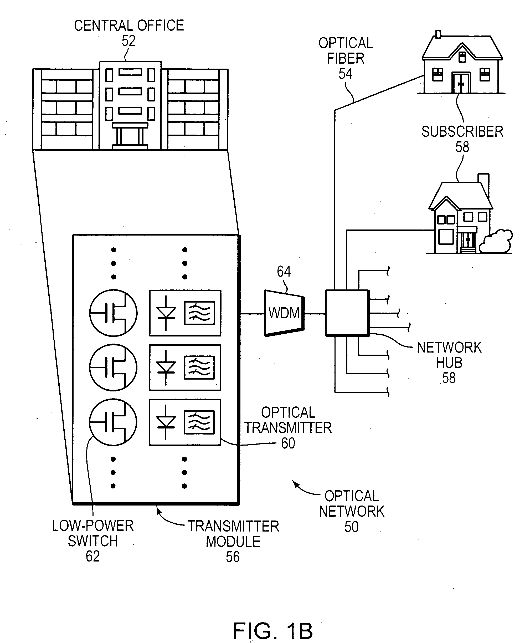
[0051]Example embodiments of the present invention provides an improved low-power means of generating high-fidelity, intensity-modulated or wavelength-switched optical signals compatible with good receiver sensitivities. Replacing a conventional continuous-wave (CW) laser and external modulation with filter-based modulation achieves the same or better performance without requiring high-fidelity low-noise input signals. This enables standard low-power and potentially noisy logic gates to be used to directly drive the optical transmitter without significant loss of waveform fidelity or ER.

[0052]Increased modulation extinction and stability, and reduced complexity, enable more sophisticated modulation while reducing size, weight, and power (SWAP), and component count, especially when implemented with scaleable implementations in the transmitter and receiver. This, in turn, improves overall reliability. Embodiments of the present invention are particul...


PUM


Abstract

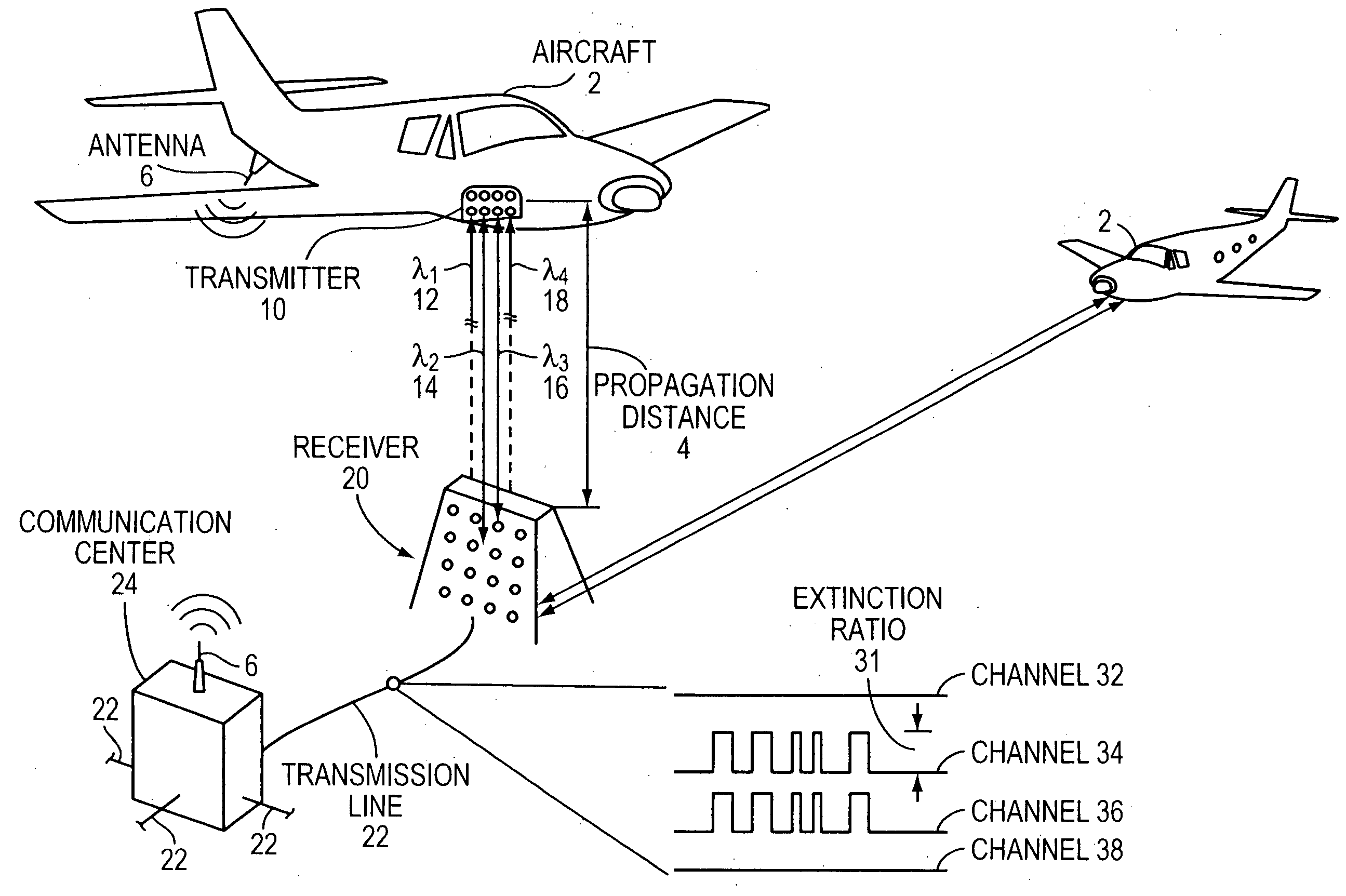
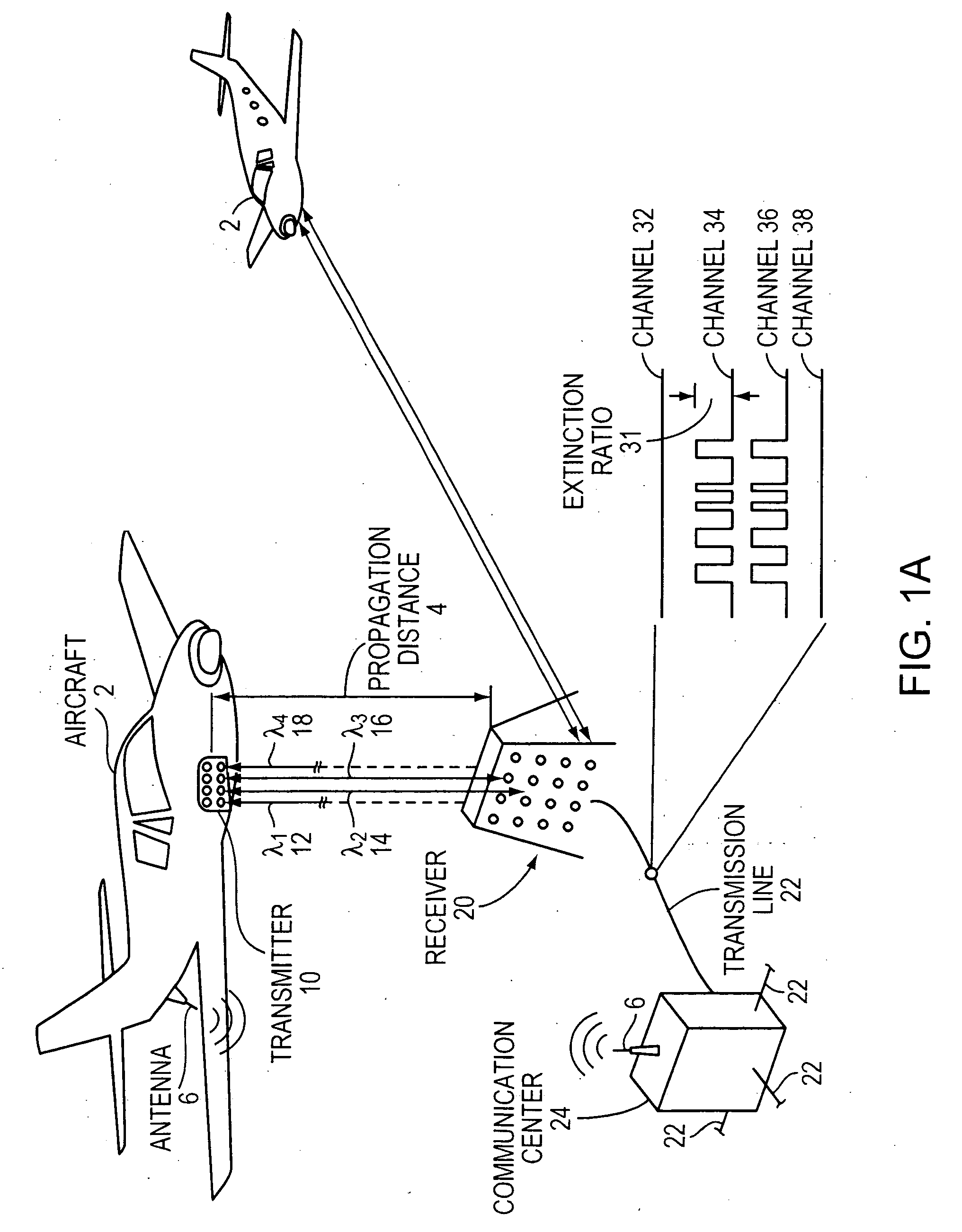
The present invention addresses the problem of transmitting optical signals with high extinction ratios using low-power drive signals. At present, low-power optical transmitters typically operate with modulation extinction ratios of, at best, about 10 dB. Embodiments of the present invention may achieve extinction ratios exceeding 20 dB using low-power drive signals of under 20 mW at data rates on the order of Gbits / sec. In addition, the modulation may be achieved with both low-power and low-fidelity drive waveforms, enabling conventional and often noisy high-speed, low-power electronics to generate high-extinction, high-fidelity optical waveforms.

Description

RELATED APPLICATION[0001]This application claims the benefit of U.S. Provisional Application No. 60 / 927,713, filed on 4 May 2007. The entire teachings of the above application are incorporated herein by reference.GOVERNMENT SUPPORT[0002]The invention was supported, in whole or in part, by a grant under Contract No. FA8721-05-C-0002 from the United States Air Force. The Government has certain rights in the invention.BACKGROUND OF THE INVENTION[0003]It is well known that good modulation extinction ratio waveforms are necessary for power-efficient implementations of optical transmitters (TXs) and receivers (RXs) for many reasons. Extinction ratio (ER), defined as the power off-to-on ratio, determines the initial distance between logical ‘0’ and ‘1’ power levels in on-off keying (OOK) modulation and may lead to multiple interferometric cross talk, which adversely impacts both time-division-multiplexed (TDM) and WDM systems (L. Fenghai, C. J. Rasmussen, and R. J. S. Pedersen, “Experiment...

Claims


Application Information

Patent Timeline
IPC IPC(8): H04B10/00
CPCH04B10/504H04B10/564
Inventor CAPLAN, DAVID O.
Owner MASSACHUSETTS INST OF TECH
Learn More