Radio Mobile Unit Location System

a mobile unit and location system technology, applied in the field of radio mobile unit location system, can solve the problems of system complexity, system cost, and certain geographically dispersed elements within the cellular network that must be synchronised or pseudo-synchronised, and achieve the effect of reducing the cost of lmu deployment, ensuring accuracy, and ensuring the accuracy of e-otd type systems

Inactive Publication Date: 2008-11-20
SEEKER WIRELESS PTY LTD
View PDF0 Cites 49 Cited by
  • Summary
  • Abstract
  • Description
  • Claims
  • Application Information

AI Technical Summary

Benefits of technology

[0060]The present invention accordingly provides a means to provide the pseudo-synchronisation for timing based positioning systems in cellular networks without incurring the high cost of LMU deployments. The resulting syn

Problems solved by technology

All time of arrival based systems however, suffer from the disadvantage that certain geographically dispersed elements within the cellular network must be synchronised, or pseudo-synchronised.
The measures taken to provide this synchronisation are arguably the key determinant of system complexity and perhaps more importantly system cost.
In the case of E-OTD, this requirement to deploy LMUs has been perhaps the greatest hurdle to the commer

Method used


Image

  • Radio Mobile Unit Location System
  • Radio Mobile Unit Location System
  • Radio Mobile Unit Location System

Examples


Embodiment Construction

[0068]The present discussion will use the GSM system to provide a concrete example but applies equally to GPRS and UMTS. The objective is to determine (without expensive LMU deployments) the relative time differences between a pair of clocked network elements such as BTSs. The time difference between BTSs is commonly referred to as the Real Time Difference (RTD). These time differences typically vary slowly over time, and therefore this is an ongoing process, the estimates have to be updated at appropriate intervals.

[0069]In the following description, there will be described a number of ways in which this synchronisation can be achieved. Networks differ in terms of the handset capabilities as well as the operator's preference for incorporating enhancements. The variety of ways presented herein enables an operator to select a technique that minimises the impact on the handsets and the network and their cost.

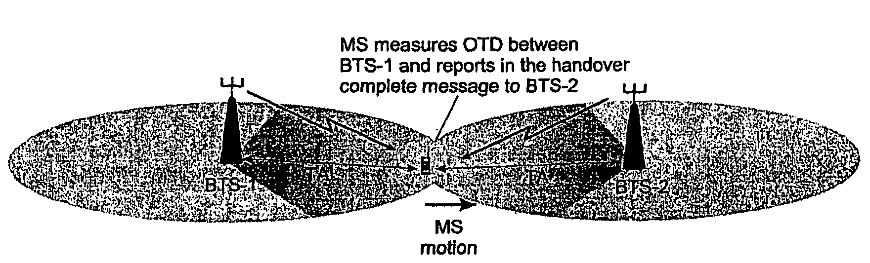
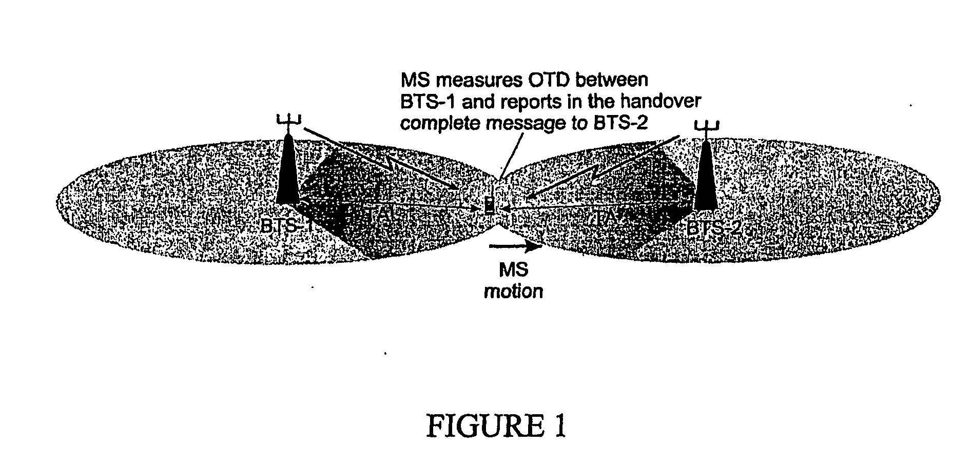
Handover Based Synchronisation Using OTD and TAs

[0070]The basis of this metho...


PUM


Abstract

Disclosed is a method for locating a mobile radio unit within a mobile radio communications network. The method provides for the calculation of network variables such as a Real Time Difference (RTD) between network elements, from measurements already available to the network from, for example, handovers between network elements. The method provides for the location of radio mobile units without having to synchronise network elements such as BTSs or LMUs.

Description

TECHNICAL FIELD[0001]This invention relates to methods and apparatus for locating a mobile radio unit within a radio communications network and to calculating various network parameters that may be used in locating the mobile radio unit.BACKGROUND TO THE INVENTION[0002]Existing cellular location systems can be classified according to the type of measurement that they employ to determine a handset's position.[0003]Cell ID (CID)[0004]Signal strength[0005]Angle of Arrival (AOA)[0006]Time of Arrival (TOA) or Time Difference of Arrival (TDOA)[0007]Of these, time arrival based systems have been shown to offer the greatest accuracy. Examples of such systems include A-GPS, U-TDOA and E-OTD. All time of arrival based systems however, suffer from the disadvantage that certain geographically dispersed elements within the cellular network must be synchronised, or pseudo-synchronised.[0008]In the case of E-OTD for instance, it is the Base Stations that need to be synchronised in order to derive ...

Claims


Application Information

Patent Timeline
IPC IPC(8): H04Q7/20G01S5/02G01S5/14G01S19/23G01S19/25G01S19/34H04W64/00
CPCG01S5/0036G01S5/021G01S5/10G01S5/14H04W64/00
Inventor DRANE, CHRISTOPHER R.MACNAUGHTAN, MALCOLM D.
Owner SEEKER WIRELESS PTY LTD
Why Eureka
Try Eureka