Apparatus, system and method for archery equipment

a technology of archery equipment and apparatus, applied in the field of apparatus, system and method of archery equipment, can solve the problems of limiting the utility of chronograph, providing a user with a very limited amount of information concerning the velocity of the arrow, and chronograph further restricting the use of the tool, so as to improve the performance of the arrow shot from the bow

Active Publication Date: 2008-11-20
FULL FLIGHT TECH
View PDF32 Cites 49 Cited by
  • Summary
  • Abstract
  • Description
  • Claims
  • Application Information

AI Technical Summary

Benefits of technology

[0018]According to another aspect, a computer readable medium is encoded with a program for execution on a processor. According to some embodiments, the program when executed on the processor provides a method of improving a performance of an arrow shot from a bow. In accordance with one embodiment, the method includes acts of collecting data with a sensor included in the arrow, the data concerning flight characteristics of the arrow when shot from the bow; and generating, based on the collected data, at least one recommended adjustment to improve a subsequent flight of the arrow.

Problems solved by technology

Further, many chronographs provide sensing elements that are located a fixed distance apart which further limits their utility.
Thus, the chronograph does not provide any measurements concerning the arrow either prior to its travel through the first sensing element or after its exit from the sensing element located the farthest down range.
Accordingly, a chronograph provides a user with a very limited amount of information concerning the velocity of the arrow.
Failure to do so will result in a failed measurement and possible destruction of the chronograph should the arrow accidentally strike a misaligned sensing element.
Currently, however, tuning is primarily accomplished by a process referred to as “paper tuning.” This approach is rather rudimentary as it involves positioning a sheet of paper downrange and relatively close to the archer (usually 10 yards or less), shooting an arrow through the center of the sheet of paper and evaluating whether the arrow's flight, and consequently the equipment adjustments, are acceptable based on the tear-pattern observed in the paper.
As a result, these designs impact the flight characteristics of the arrow, at least, because they effect the weight distribution and balance of the arrow shaft.
In addition, these devices are generally not suitable for removal from the arrow shaft and reuse with a different shaft.

Method used


Image

  • Apparatus, system and method for archery equipment
  • Apparatus, system and method for archery equipment
  • Apparatus, system and method for archery equipment

Examples


Embodiment Construction

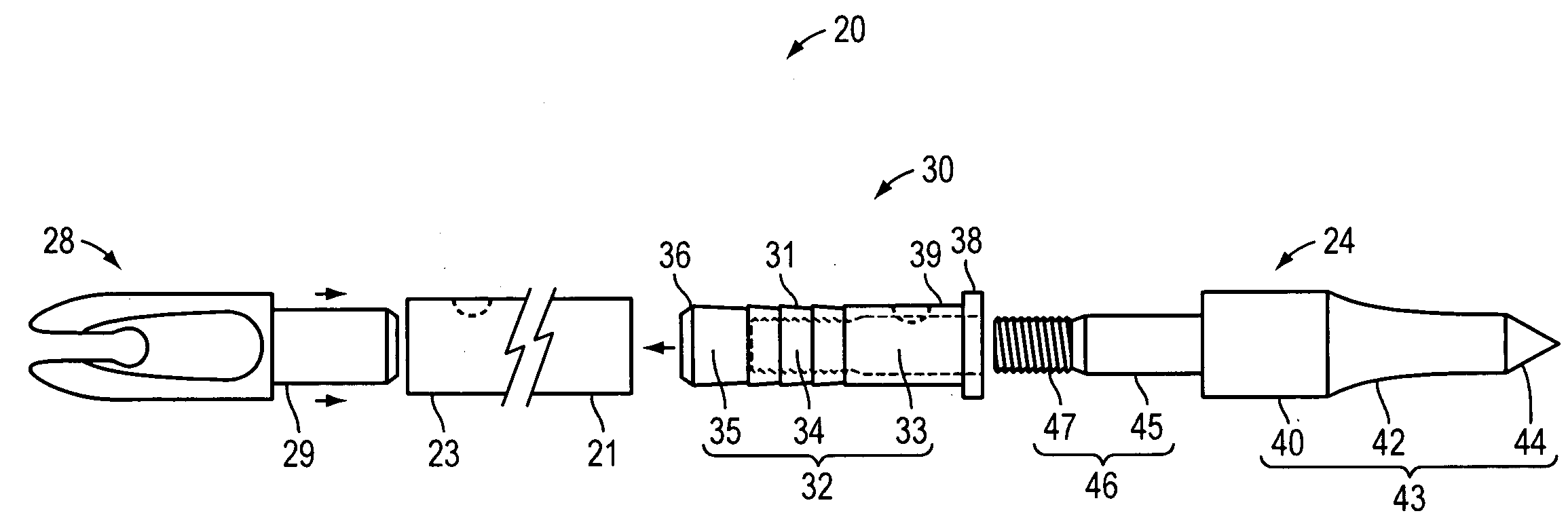
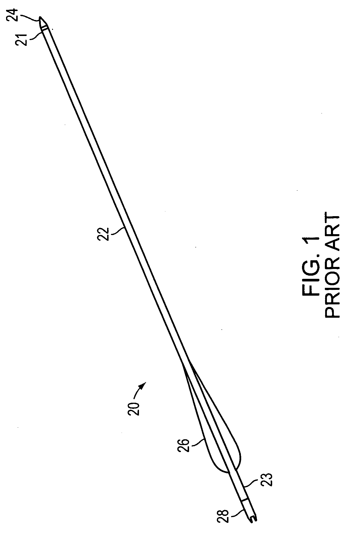
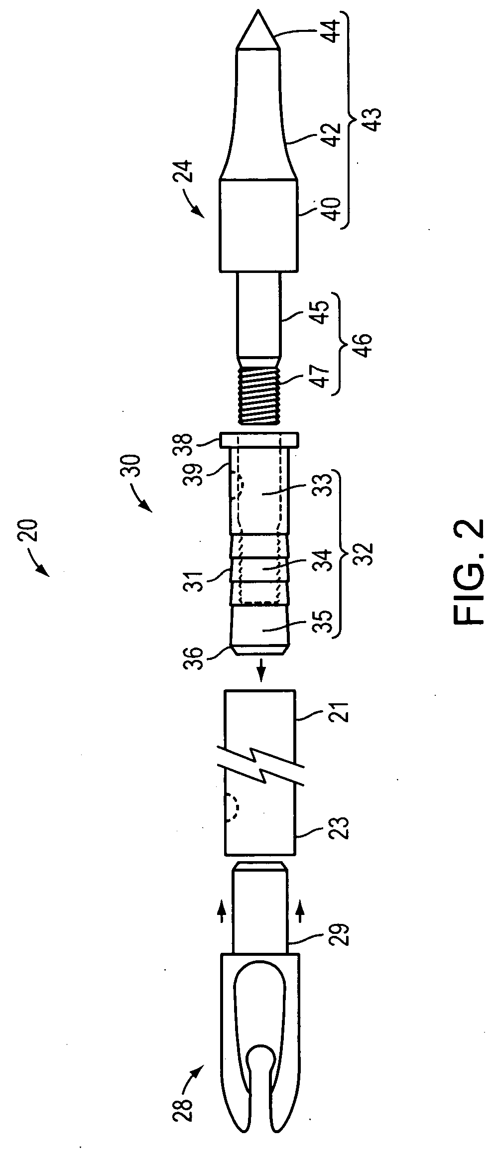
[0042]FIG. 1 illustrates a conventional arrow 20 suitable for use with various embodiments of the invention described below. The arrow 20 includes a shaft 22, a tip 24, vanes 26, and a nock 28. In one embodiment the shaft 22 is a tubular shaft with a hollow central region located concentrically relative to the exterior walls of the shaft. The tip 24 may be provided in a variety of configurations including field / target points, fixed-blade broadheads, mechanical broadheads and any other tips that are adapted to secure at the distal end 21 of the arrow. The tip 24 may be secured to the arrow shaft or provided as an integral component thereof. For example, in some embodiments, an adapter 30 may be employed to attach to the shaft 22 and receive the tip 24. In one embodiment, the arrow includes an adapter 30, which is located within the shaft 22 at the distal end 21, and the tip 24 is secured to the adapter 30. According to one embodiment, the adapter 30 is inserted within the shaft 22 (e...


PUM


Abstract

An apparatus is configured for inclusion in an arrow, where the apparatus includes a device configured to provide feedback to a user concerning the arrow shot from a bow, and a processor coupled to the device, the processor configured to control an operation of the device at least during a flight of the arrow.

Description

RELATED APPLICATIONS[0001]The application is a continuation-in-part of U.S. application Ser. No. 12 / 016,019, entitled “SYSTEMS AND METHODS FOR ARCHERY EQUIPMENT,” filed Jan. 17, 2008, which claims the benefit under 35 U.S.C. § 119(e) to U.S. Provisional Application Ser. No. 60 / 881,125, entitled “SYSTEMS AND METHODS FOR ARCHERY EQUIPMENT,” filed on Jan. 18, 2007, each of the preceding applications is herein incorporated by reference in its entirety.BACKGROUND OF THE INVENTION[0002]1. Field of the Invention[0003]Embodiments of the invention generally relate to archery equipment. More specifically, at least one embodiment, relates to apparatus, systems and methods employing an arrow-mounted electronic apparatus.[0004]2. Discussion of Related Art[0005]The velocity of an arrow shot from a bow may be measured to determine the effectiveness of the archery equipment, for example, a combination of a particular bow and arrow.[0006]A ballistic-type chronograph is typically employed to measure ...

Claims


Application Information

Patent Timeline
Patent Type & Authority Applications(United States)
IPC IPC(8): F42B6/04F42B12/36
CPCF41B5/14F42B6/04F42B6/06F42B6/08F42B12/385A63B47/008A63B69/00A63B69/3658
Inventor DONAHOE, ROBERT V.
Owner FULL FLIGHT TECH
Why Eureka
Try Eureka