Numerical control method for five-axis processing machine

a technology of processing machine and numerical control method, which is applied in the direction of electric programme control, program control, instruments, etc., can solve the problems of excessive cutting into processing objects, unstable operation, and restricted speed of movement, so as to prevent unstable operation and prevent excessive cutting

Active Publication Date: 2008-11-20
FANUC LTD
View PDF4 Cites 24 Cited by
  • Summary
  • Abstract
  • Description
  • Claims
  • Application Information

AI Technical Summary

Benefits of technology

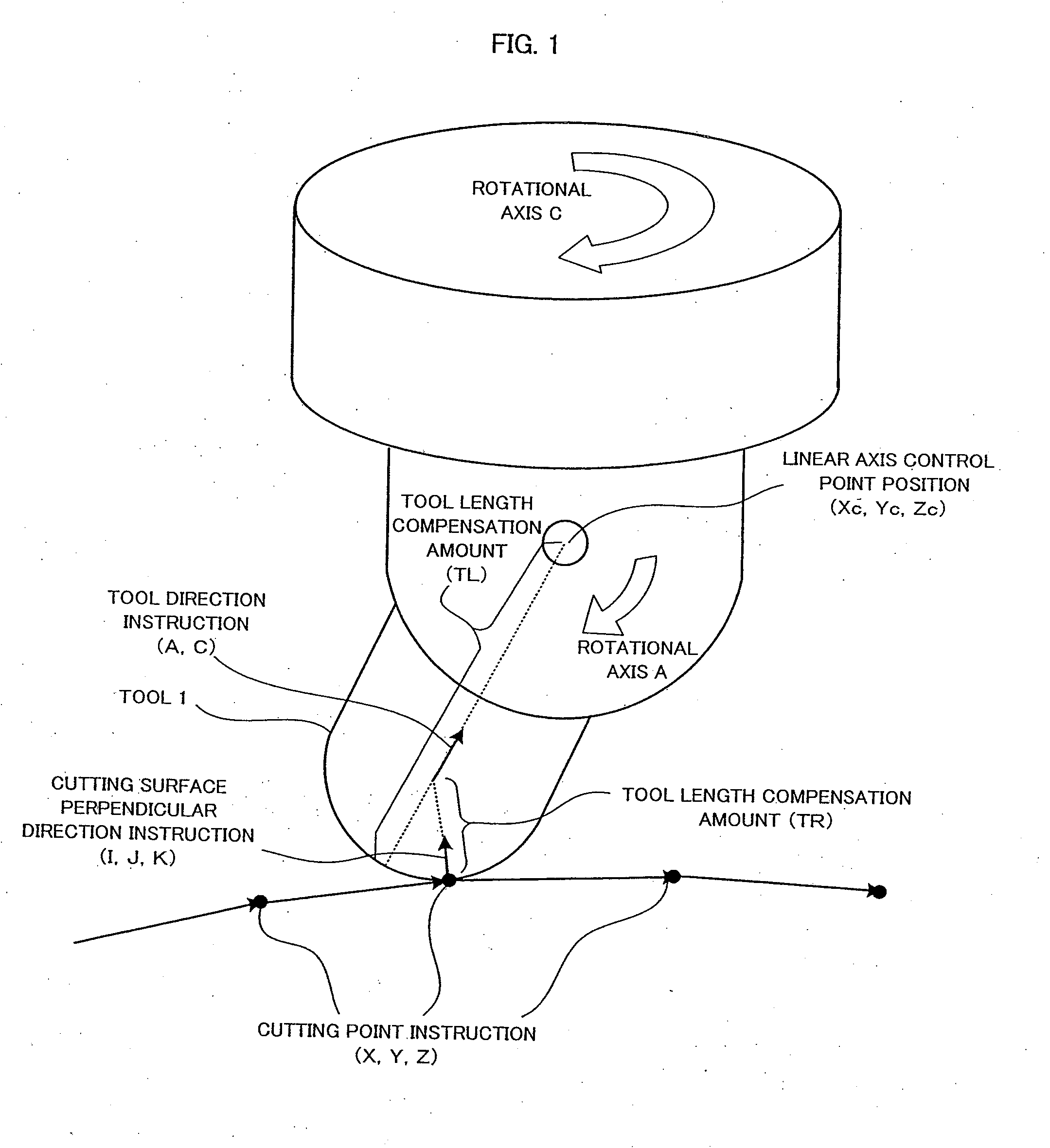
[0066]Therefore, it is an object of the present invention to provide a method of controlling a five-axis processing machine having three linear axes and two rotational axes whereby it is possible to prevent unstable movement in the vicinity of a singular point and excessive cutting into a processing object, as described above.
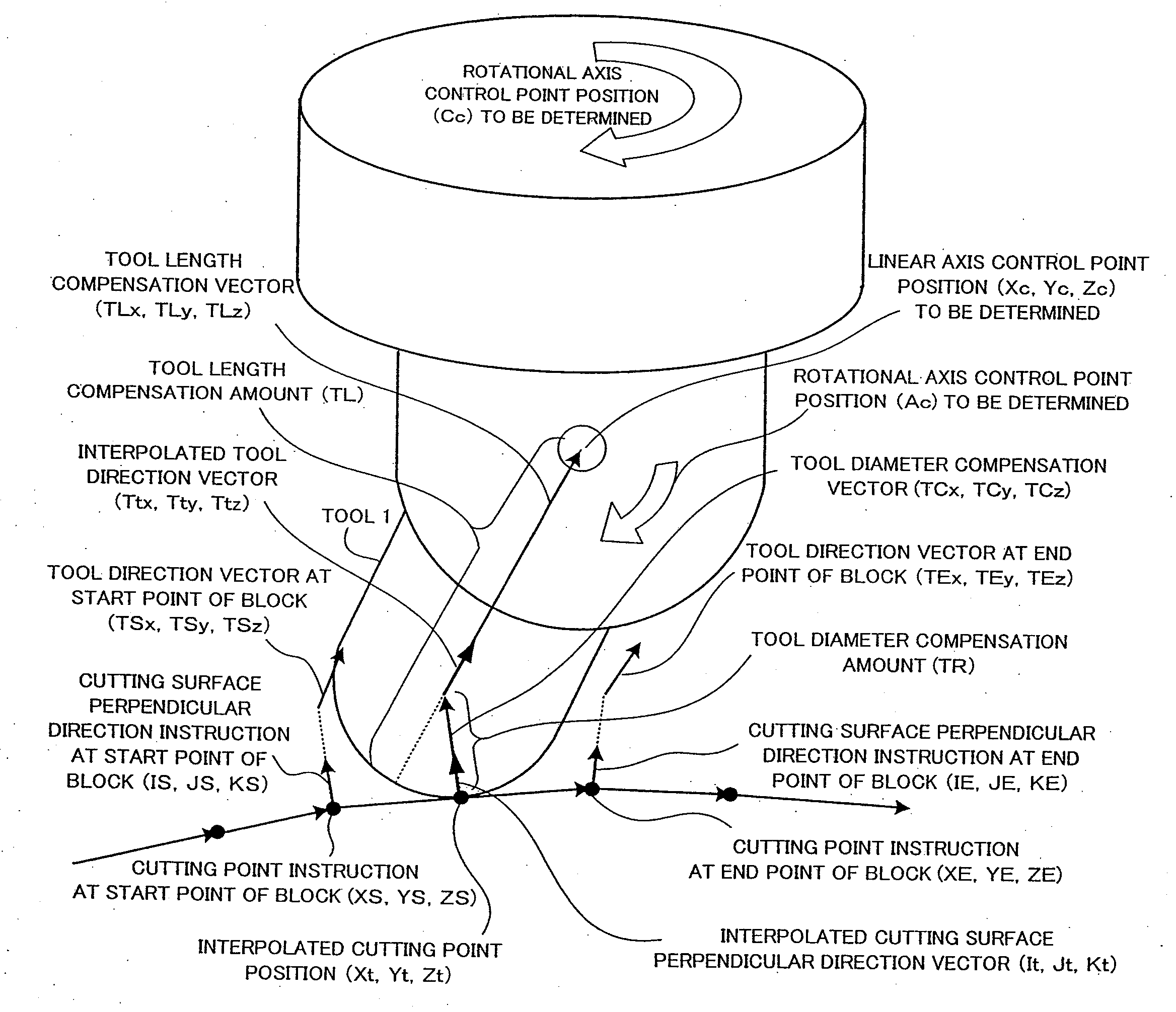
[0068]In a second mode of a numerical control method which controls a five-axis processing machine according to the present invention, a milling tool which has a corner radius section is used, control points for the respective axes are determined at respective interpolation cycles, based on a predetermined tool diameter compensation amount, a corner radius compensation amount and tool length compensation amount which are set in advance, and also on a processing program in which cutting points, a cutting surface perpendicular direction and a tool direction are instructed, and in which the respective axes are driven and controlled to positions of the control points thus determined. This method further comprises step of determining, at each interpolation cycle, an interpolated cutting point position, an interpolated cutting surface perpendicular direction vector, an interpolated tool direction vector, a tool diameter compensation vector, a corner radius compensation vector, and a tool length compensation vector, based on the tool diameter compensation amount, corner radius compensation amount and tool length compensation amount which are set in advance, and also on the cutting point, cutting surface perpendicular direction and tool direction which are instructed by a processing program; step of determining, in cases where an angle formed between the interpolated-cutting surface perpendicular direction vector and the interpolated tool direction vector is smaller than a predetermined first set value, a linear axis control point by taking the tool diameter compensation vector for the current interpolation cycle as the tool diameter compensation vector calculated in the interpolation cycle immediately before the angle become smaller, and by adding this tool diameter compensation vector, and the corner radius compensation vector and the tool length compensation vector, to the interpolated cutting point position; and step of determining, in cases where the angle formed between the interpolated cutting surface perpendicular direction vector and the interpolated tool direction vector has become greater than the first set value in subsequent interpolation cycles, the linear axis control point by adding the tool diameter compensation vector, the corner radius compensation vector and the tool length compensation vector which are determined in the interpolation cycle immediately after the angle has become greater, to the interpolated cutting point position, and moving the linear axis control point thus determined at a pre-designated speed. By means of the numerical control method according to this mode, it is possible to stabilize the processing in the proximity of a singular point, where operation becomes unstable.
[0069]In a third mode of a numerical control method for controlling a five-axis processing machine according to the present invention, a milling tool which does not have a corner radius section or a ball end mill is used, linear axis control points and rotational axis control points are determined at respective interpolation cycles, based on a tool diameter compensation amount and a tool length compensation amount which are set in advance, and also on cutting points, a cutting surface perpendicular direction and a tool direction which are instructed by a processing program, and in which the respective axes are driven and controlled to positions of the respective control points thus determined. This method further comprises step of determining a cutting point position and a linear axis control point respectively at a start point and an end point for each of blocks thereof; and step of assuming that the linear axis control point at the end point of the current block is equal to the linear axis control point at the start point of the current block so that movement of the linear axis in accordance with the instructions in the current block does not occur, when judgment is made that a distance between the linear axis control points at the start point and the end point of the block is smaller than a predetermined second set value, and that a distance between the cutting point positions at the start point and the end point of the block is greater than a predetermined third set value, or when judgment is made that a ratio of the distance between the linear axis control points at the start point and the end point of the block to the distance between the cutting point positions at the start point and the end point of the block is less than a predetermined fourth set value. By means of the numerical control method according to this mode, it is possible to prevent the occurrence of excessive cutting in the proximity of a singular point where the linear axes move in a loop shape.
[0071]In a fifth mode of a numerical control method for controlling a five-axis processing machine, a milling tool which has a corner radius section is used, linear axis control points and rotational axis control points are determined at respective interpolation cycles, based on a predetermined tool diameter compensation amount, a corner radius compensation amount and a tool length compensation amount which are set in advance, and also on cutting points, a cutting surface perpendicular direction and a tool direction which are instructed by a processing program, and in which the respective axes are driven and controlled to positions of the respective control points thus determined. This method further comprises step of determining a cutting point position and a linear axis control point respectively at a start point and an end point for each of blocks thereof; and step of assuming that the linear axis control point at the end point of the current block is equal to the linear axis control point at the start point of the current block so that movement of the linear axis in accordance with the instructions in the current block does not occur, when judgment is made that a distance between the linear axis control points at the start point and the end point of the block is smaller than a predetermined second set value, and that a distance between the cutting point positions at the start point and the end point of the block is greater than a predetermined third set value, or when judgment is made that a ratio of the distance between the linear axis control points at the start point and the end point of the block to the distance between the cutting point positions at the start point and the end point of the block is less than a predetermined fourth set value. By means of the numerical control method according to this mode, it is possible to prevent the occurrence of excessive cutting in the proximity of a singular point where the linear axes move in a loop shape.
[0073]By adopting the composition described above, the present invention is able to prevent unstable operation arising at singular points where the interval between instructions in the cutting point instructions is small but the movement distance of the linear axis control point is large, in a five-axis processing machine having three linear axes and two rotational axes. Furthermore, it is also possible to prevent excessive cutting arising at a singular point where the interval between the positions of the cutting point instructions is large but the movement of the control point when processing between these points is small.

Problems solved by technology

By this means, if the speed and the acceleration of the respective joints becomes excessively large in the proximity of a singular point, then the speed of movement is restricted as far as possible, while satisfying the required accuracy in respect of error in the path of travel.
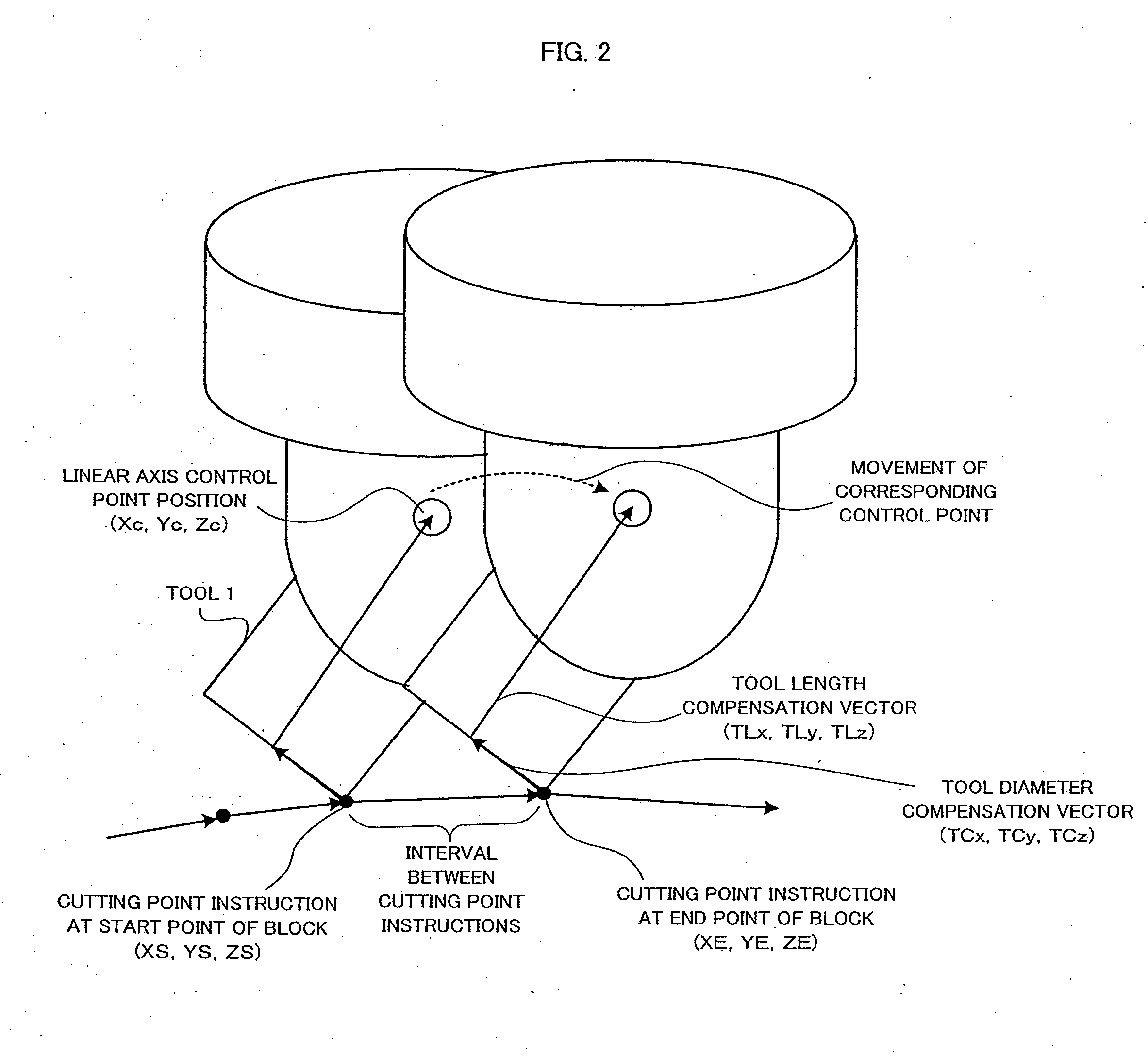
In the proximity of a singular point of this kind, where there is a large difference between the interval between the instructed control points and the corresponding movement of the control point, undesirable situations, such as unstable operation and / or excessive cutting into the processing object, may occur.
Since the tool diameter compensation vector (TCx, TCy, TCz) changes significantly in this way, then the control point (Xc, Yc, Zc) also changes, and the operation becomes unstable.
As a result, there is a problem in that the tool cuts into the processing object, or the like.

Method used


Image

  • Numerical control method for five-axis processing machine
  • Numerical control method for five-axis processing machine
  • Numerical control method for five-axis processing machine

Examples


first embodiment

[0095]To begin with, a numerical control method according to the present invention which eliminates operational instability in the proximity of the singular point 1 will be described with reference to FIG. 12 and FIG. 13.

[0096]FIG. 12 is a diagram describing a process for determining a singular point 1, and a process for avoiding unstable movement when the singular point 1 is determined.

[0097]As described previously, when the interpolated cutting surface perpendicular direction vector (It, Jt, Kt) is determined and the interpolated tool direction vector (Ttx, Tty, Ttz) is determined, then the angle α formed between these two vectors is found and it is judged whether or not this angle α is smaller than a previously set parameter value (Prm(α)). If the angle α is smaller than the set value (Prm(α)), then this means that the front end plane of the square end mill or the radius mill, and the processing plane are in a state close to parallel, and hence there is a high possibility of sati...

second embodiment

[0131]FIG. 14 is an illustrative diagram of processing for determining a singular point 2 and processing for avoiding movement which causes excessive cutting when a singular point 2 has been determined, as implemented in a numerical control method according to the present invention.

[0132]The second embodiment relates to an example where the tool used is a ball end mill. In this FIG. 14, since the tool length compensation vector (TLSx, TLSy, TLSz) at the start point of a block and the tool length compensation vector (TLEx, TLEy, TLEz) at the end point of the block are close together in the proximity of a singular point 2, then for the sake of convenience, they are represented by the same arrow and position. Similarly, since the linear axis control point (XSc, YSc, ZSc) at the start point of a block and the linear axis control point (XEc, YEc, ZEc) at the end point of the block are close together in the proximity of a singular point 2, then for the sake of convenience, they are repres...


PUM


Abstract

If the angle α formed between the interpolated cutting surface perpendicular direction vector (It, Jt, Kt) and the interpolated tool direction vector (Ttx, Tty, Ttz) becomes smaller, movement of a tool becomes unstable. In this case, the tool diameter compensation vector (TCx, TCy, TCz) is set to the tool diameter compensation vector calculated in the immediately previous interpolation cycle, thereby preventing unstable movement. Further, in case of a block instruction where a distance between positions in cutting point instructions is large whereas distance of movement of linear axis control point is small, an excessive cutting may occur. To deal with this problem, movement of linear axis control point in a current block is stopped or converted into linear movement so as to prevent a loop-shaped movement of the linear axis control point.

Description

BACKGROUND OF THE INVENTION[0001]1. Field of the Inventionhose[0002]The present invention relates to a numerical control method for controlling a five-axis processing machine having two rotational axes and three linear axes, and also relates to operational control in the proximity of singular points where there is a possibility of the occurrence of unstable movement.[0003]2. Description of the Related Art[0004]There is already known a five-axis processing machine which carries out processing by moving a tool relatively in three linear axis directions with respect to a workpiece (processing object), as well as inclining the tool relatively with respect to the workpiece about two rotational axes. For example, there is known a processing method using a five-axis processing machine which processes a curved surface by performing curve interpolation, on the basis of command point sequence data created by a CAD / CAM apparatus or an associated apparatus, and a command vector sequence which i...

Claims


Application Information

Patent Timeline
Patent Type & Authority Applications(United States)
IPC IPC(8): G05B19/19
CPCG05B19/404G05B19/4103G05B2219/35158G05B2219/49344G05B2219/50297G05B2219/50336
Inventor OTSUKI, TOSHIAKIIDE, SOICHIROMIYAZAKI, TAKESHI
Owner FANUC LTD
Why Eureka
Try Eureka