Portable welding smog disposing machine

a welding smog and dismantling machine technology, applied in the direction of shielding gas supply/evacuation device, separation process, filtration separation, etc., can solve problems such as fire or gas explosion, and achieve the effect of convenient disassembly and effective maintenance of good air quality in the working environmen

Inactive Publication Date: 2008-11-27
CHENG CHIEH YUAN +1
View PDF8 Cites 1 Cited by
  • Summary
  • Abstract
  • Description
  • Claims
  • Application Information

AI Technical Summary

Benefits of technology

[0006]Thus, the embers produced during electric welding will be sucked to directly drop into the ember obstruction device through the through hole of the front accommodating chamber to be collected therein for preventing the embers from getting into the machine box and potentially causing a fire or gas explosion. In addition, the door plank can be conveniently disassembled from the machine box for facilitating pouring out the embers and washing clean the ember obstruction device. Moreover, the filthy air produced by the embers will be filtrated repeatedly by the filter plate set in the accommodating space; therefore, the air exhausted out of the machine box is unpolluted, able to effectively maintain good quality of the air in the working environment.

Problems solved by technology

Thus, the embers produced during electric welding will be sucked to directly drop into the ember obstruction device through the through hole of the front accommodating chamber to be collected therein for preventing the embers from getting into the machine box and potentially causing a fire or gas explosion.
Moreover, the filthy air produced by the embers will be filtrated repeatedly by the filter plate set in the accommodating space; therefore, the air exhausted out of the machine box is unpolluted, able to effectively maintain good quality of the air in the working environment.

Method used


Image

  • Portable welding smog disposing machine
  • Portable welding smog disposing machine
  • Portable welding smog disposing machine

Examples


Embodiment Construction

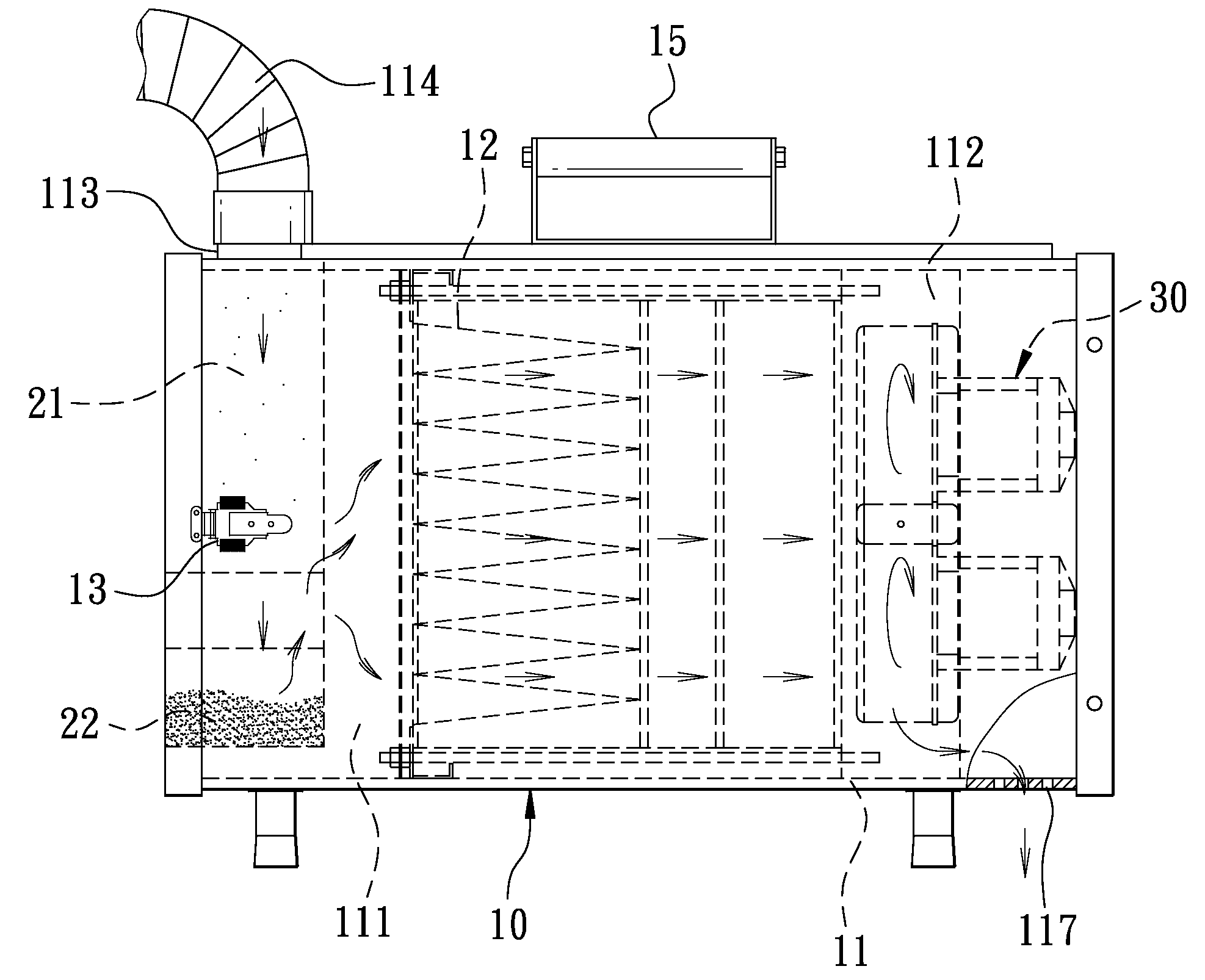
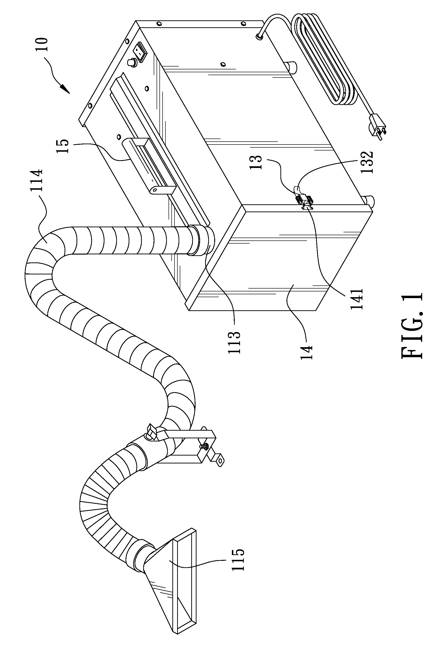
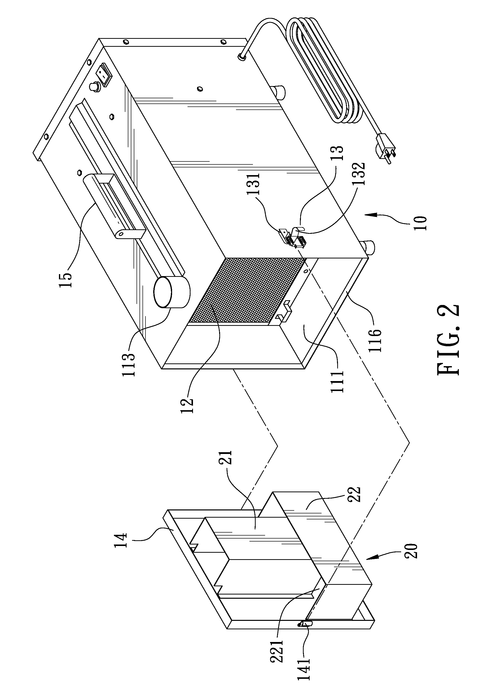
[0011]A preferred embodiment of a portable welding smog-disposing machine in the present invention, as shown in FIGS. 1, 2 and 3, includes a machine box 10, an ember obstruction device 20 and plural blowers 30 preset in number.

[0012]The machine box 10 is formed in the interior with an accommodating space 11 having an intermediate preset portion disposed with a filter plate set 12, which partitions the accommodating space 11 into a front accommodating chamber 111 and a rear accommodating chamber 112. The front accommodating chamber 111 has its topside bored with a through hole 112 extending upward and fitted thereon with an air pumping pipe 114 that is contractible and flexible to be bent freely. The air-pumping pipe 114 has its outer end connected with a funnel-shaped pumping pipe head 115 for facilitating sucking embers. The front accommodating chamber 111 has its front side formed with an opening 116, and the machine box 10 has its opposite sides respectively fixed thereon with a ...


PUM

PropertyMeasurementUnit
flexibleaaaaaaaaaa
timeaaaaaaaaaa

Abstract

A portable welding smog disposing machine includes a machine box formed with an accommodating space disposed at an intermediate portion with a filter plate set, which partitions the accommodating space into a front and a rear accommodating chamber. The front accommodating chamber has its topside bored with a through hole extending upward and its front side formed with an opening having a door plank pivotally assembled thereon. An ember obstruction device is fixed on the inner side of the door plank and received inside the front accommodating chamber. By so designing, the embers produced during electric welding will be pumped to directly drop into the ember obstruction device through the through hole to be collected therein so as to prevent the embers from getting into the machine box.

Description

BACKGROUND OF THE INVENTION[0001]1. Field of the Invention[0002]This invention relates to a portable welding smog-disposing machine, particularly to one able to effectively dispose the smog and the embers produced during carrying out electric welding work.[0003]2. Description of the Prior Art[0004]As commonly known, when a metal welding factory carries out metal welding work, such as argon welding, electric welding and thermal treatment, a great quantity of welding smog containing heavy metals like lead, manganese and nickel will be produced. Under the circumstances, the operator who works in a working environment full of welding smog is likely to inhale too much heavy metals in the welding smog, thus not only polluting the working environment but endangering the operator's health as well. For the present, many factories can hardly achieve good effect in ventilation on account of nearby buildings. Although an operator wearing a breathing protector can avoid inhaling too much heavy m...

Claims


Application Information

Patent Timeline
Patent Type & Authority Applications(United States)
IPC IPC(8): B01D29/05
CPCB23K9/325
Inventor CHENG, CHIEH-YUAN
Owner CHENG CHIEH YUAN
Why Eureka
Try Eureka