Planar motor

a planar motor and motor housing technology, applied in the direction of dynamo-electric machines, electrical apparatus, magnetic circuits, etc., can solve the problems of difficult placement and high cost of magnet array production, and achieve the effect of easy production

Active Publication Date: 2008-11-27
ETEL SA
View PDF9 Cites 21 Cited by
  • Summary
  • Abstract
  • Description
  • Claims
  • Application Information

AI Technical Summary

Benefits of technology

[0006]Example embodiments of the present invention provide a planar motor which is easier to produce, particularly as fa...

Problems solved by technology

Such a magnet array is quite costly to produce, since a great number of magnets with very narrow dimensional tolerances are necessary, whose placement is difficult because of...

Method used


Image

  • Planar motor
  • Planar motor

Examples


Embodiment Construction

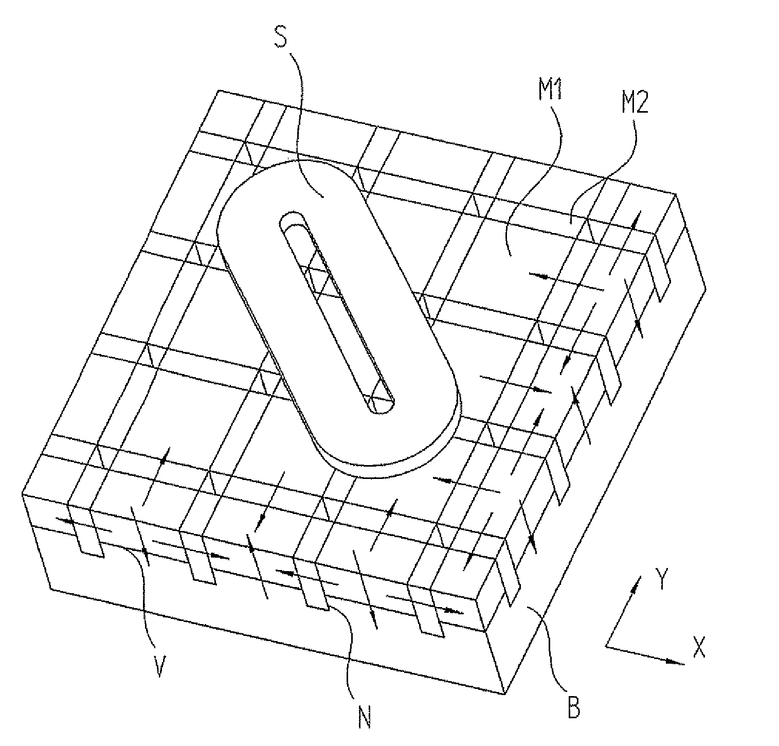
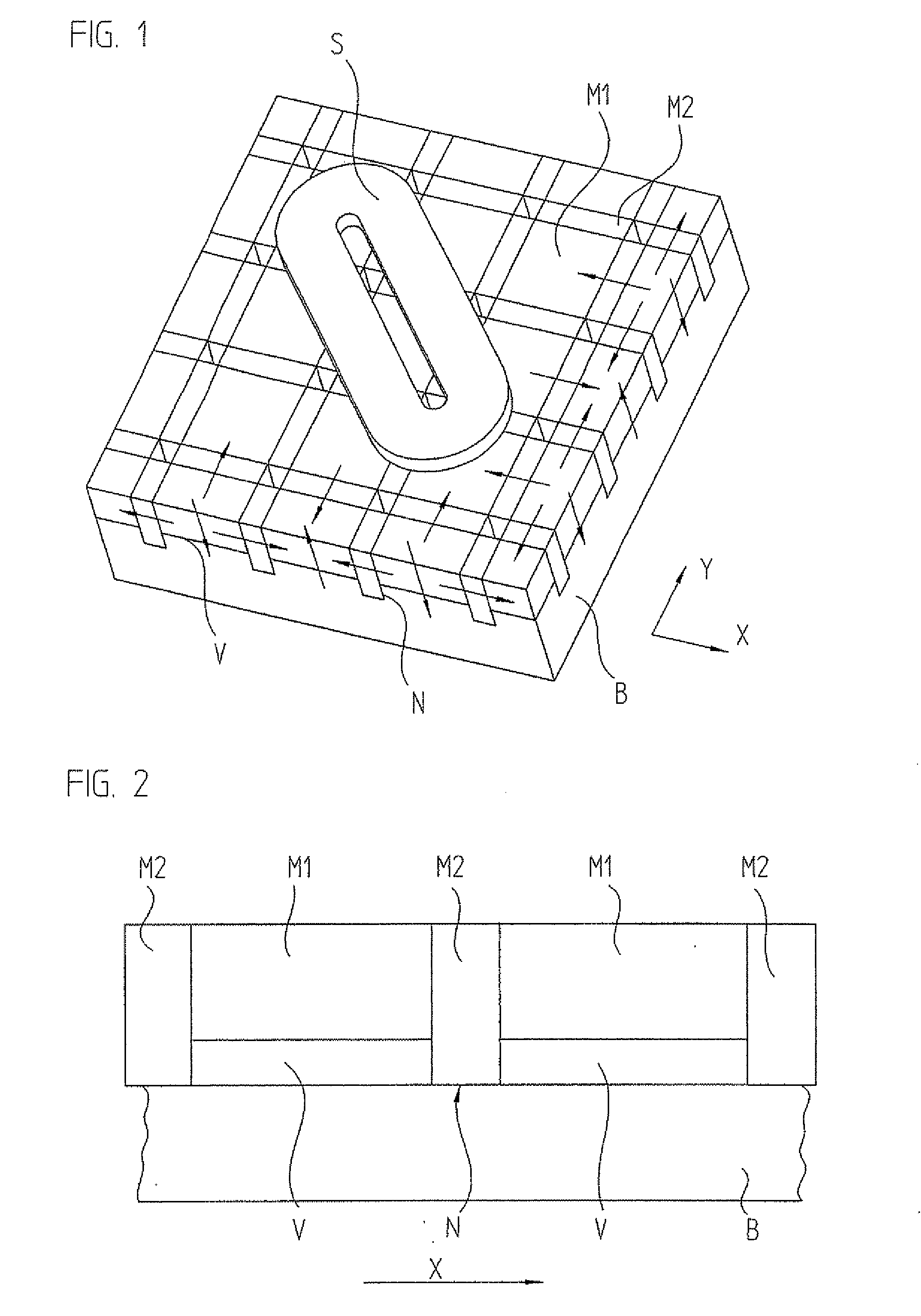
[0027]FIG. 1 is a schematic perspective view of a planar motor according to an example embodiment of the present invention, and FIG. 2 is a schematic cross-sectional view of the planar motor with direction of view in the Y-direction. Reference is made to both figures in the following description.

[0028]The planar motor has a stator in which, disposed on a base element B in plane XY are substantially cuboidal first magnets M1 whose magnetization is perpendicular to plane XY and which are disposed at evenly spaced intervals and with alternating polarity in a first direction X and in a second direction Y. In addition, the planar motor has substantially cuboidal second magnets M2 whose magnetization is parallel to plane XY in the X direction or Y direction, and which in each case are disposed with alternating polarity in first direction X and second direction Y between first magnets M1. The magnetization directions of magnets M1, M2 are indicated with arrows in the area of the visible cu...


PUM


Abstract

A planar motor includes a flat base element arranged in a plane, and substantially cuboidal first magnets arranged on the base element whose magnetization is perpendicular to the plane and which are arranged at evenly spaced intervals and with alternating polarity in a first direction and in a second direction. The planar motor also includes substantially cuboidal second magnets whose magnetization is parallel to the plane and which are disposed with alternating polarity in the first direction and second direction between the first magnets, so that each first magnet is surrounded by four second magnets. The first magnets are disposed on protrusions of the base element.

Description

CROSS-REFERENCE TO RELATED APPLICATIONS[0001]The present application claims priority to Application No. 10 2007 024 602.3, filed in the Federal Republic of Germany on May 25, 2007, which is expressly incorporated herein in its entirety by reference thereto.FIELD OF THE INVENTION[0002]The present invention relates to a planar motor. Such planar motors are used, e.g., for positioning a load in a plane.BACKGROUND INFORMATION[0003]For example, planar motors are familiar from the electronics industry where, when manufacturing integrated circuits, semiconductor wafers must be positioned with extreme accuracy in a plane, for example, in order to process the wafers photolithographically.[0004]U.S. Pat. No. 6,188,147 describes such a planar motor, which features a planar base element having pyramid-shaped protrusions on which magnets having different directions of magnetization are mounted, so that in sum, a magnetic field perpendicular to the base element is obtained over each of the pyrami...

Claims


Application Information

Patent Timeline
IPC IPC(8): H02K41/02
CPCH02K41/031H02K2201/18H02K1/278
Inventor CARDON, VINCENTMOREL, JEAN-PIERRE
Owner ETEL SA
Why Eureka
Try Eureka