Apparatus of nuclear magnetic resonance measurement for continuous sample injection

a nuclear magnetic resonance and measurement apparatus technology, applied in the direction of magnetic measurement, measurement devices, instruments, etc., can solve the problems of difficult application of approaches, difficulty in ensuring the uniformity of applied electromagnetic waves, so as to reduce the time for measuring, suppress irregular magnetic fields, and eliminate sharp edges

Inactive Publication Date: 2008-11-27
HITACHI LTD
View PDF8 Cites 3 Cited by
  • Summary
  • Abstract
  • Description
  • Claims
  • Application Information

AI Technical Summary

Benefits of technology

[0010]An object of the present invention is to provide an NMR measurement apparatus suitable for NMR measurement for continuous sample injection, using a sample tube having a structure capable of ensuring the uniformity in the static magnetic field and ensuring the uniformity in the applied electromagnetic wave.
[0015]Typically, in order to detect a good FID signal, a shim coil built in the magnet is used for adjustment such that the magnetic field produced by the magnet is the uniform static magnetic field. However, the use of the shim coil for adjustment to remove distortion in the magnetic field developed at the interface between the sample and the sample tube takes much time and labor. Therefore, a difference between the magnetic susceptibility of the sample tube portion around the sample and the magnetic susceptibility of the sample (in particular, the sample solvent) is reduced to thereby reduce the distortion in the magnetic field developed at the interface between the sample and the sample tube, thus increase a relaxation time for the detected FID signal, and thus reduce a spectral line width.
[0018]In order to make uniform the magnetic field distribution of the irregular magnetic field, it is necessary to produce the magnetic field having the order and geometrical characteristics equivalent to the produced magnetic field and thereby cancel off the irregular magnetic field. In order to cancel off the magnetic field distribution of higher order, it is required that a shim coil of higher order be prepared for magnetic field adjustment in the vicinity of the sample. However, it is desirable that the irregular magnetic field of higher order be suppressed due to the fact that the number of dimensions of the shim coil is limited and that the magnetic field adjustment using the shim coil of higher order takes much time. Therefore, as shown in FIG. 9, a curved surface structure can be used for the interface between the sample and the container to eliminate a sharpness in the interface and suppress the irregular magnetic field having geometrical characteristics of higher order.
[0019]Even if there is a difference in the magnetic susceptibility between the container and the sample solvent, the container using the curved surface structure for the interface between the sample and the container suppresses the irregular magnetic field of higher order, and thus is effective for measurement of the sample that changes in the magnetic susceptibility due to a change in solvent concentration. The NMR measurement for continuous sample injection often includes measurement that involves changing solution conditions, and thus, the container using the curved surface structure for the interface between the sample and the container is effective. The irregular magnetic field distribution of higher order can be suppressed regardless of the magnetic susceptibility of the solvent sample, and thus, the repetition times of magnetic field adjustments for the NMR titration measurement and the time therefor can be reduced.
[0020]In addition, the container having the cylindrical shape and flat surface at the interface with the sample may be used for measurement at a constant water concentration (or deuterium oxide concentration) at a constant temperature in which even a change in the solution conditions causes little change in the magnetic susceptibility of the solvent, or the like. The container having the flat interface has the merit of being easy to fabricate and thus reducing manufacturing costs, as compared to the curved surface structure.
[0021]The present invention enables the NMR measurement that maintains the uniformity in the static magnetic field for the NMR measurement for continuous sample injection and high uniformity in the electromagnetic wave applied to the sample, and the high uniformity in the applied electromagnetic wave can be achieved regardless of the configuration of the antenna or the presence or absence of an RF shield. In addition, the length of the container that stores the sample required for the NMR measurement is equal to or less than the length of the antenna coil, and this enables a reduction in the target sample.

Problems solved by technology

The conventional sample tube configuration and antenna arrangement requires a sample having a larger volume than the volume of the region in which a signal is to be actually detected, and thus raises measuring costs for measurement of scarce samples or isotope-labeled protein.
In addition, the approach of coating the top and bottom of the sample with the substance having the adjusted magnetic susceptibility is effective for measurement where the sample tube containing the sample is placed in the uniform static magnetic field; however, this approach is difficult to apply to the nuclear magnetic resonance measurement for continuous sample injection, in which the sample is injected and ejected directly from the outside.
Further, the conventional sample tube has difficulty in ensuring the uniformity in the applied electromagnetic wave and the uniformity in the magnetic field only with the sample tube.
In addition, when the position of the sample is far away from the location L of the end of the antenna, the sample receives the electromagnetic wave from the antenna although it is feeble.

Method used


Image

  • Apparatus of nuclear magnetic resonance measurement for continuous sample injection
  • Apparatus of nuclear magnetic resonance measurement for continuous sample injection
  • Apparatus of nuclear magnetic resonance measurement for continuous sample injection

Examples


first embodiment

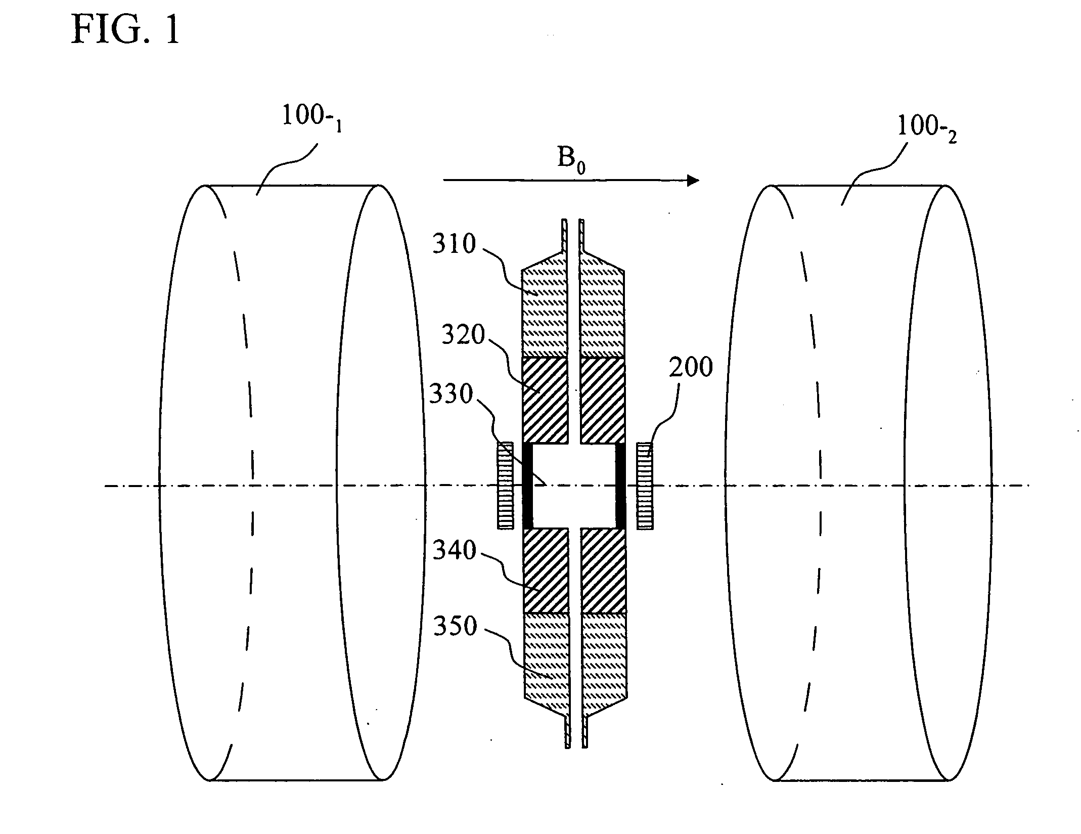
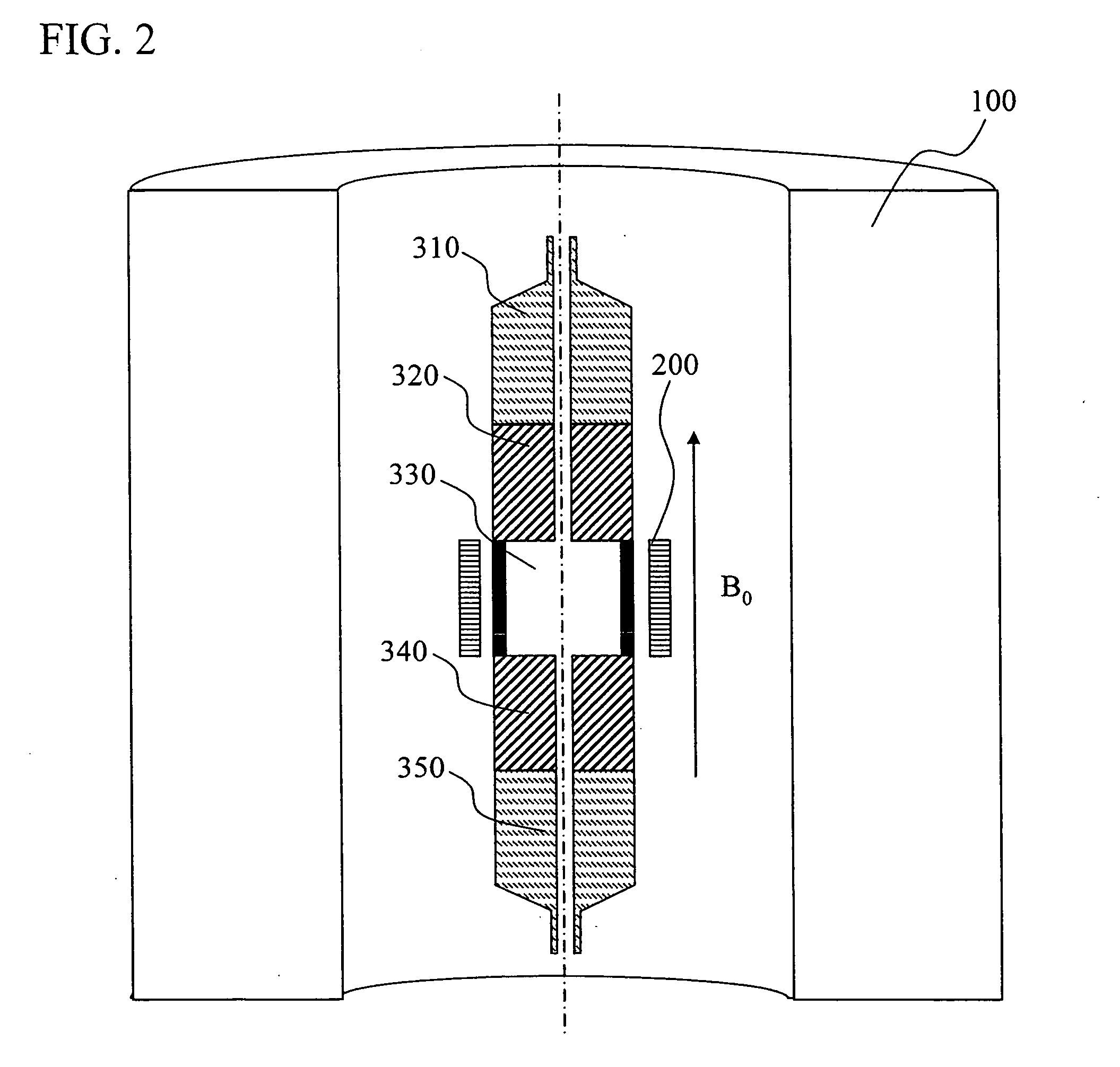
[0032]FIG. 1 is a view of the arrangement of a sample tube and an antenna for a split magnet. As shown in FIG. 1, magnets 100 that produce a magnetic field are mounted, and an antenna 200 for detecting a nuclear magnetic resonance signal is mounted in a uniform magnetic field region located in the vicinity of the magnet. FIG. 2 is a view of the arrangement of the sample tube and the antenna for an integral magnet as used as the magnet 100. Even with magnets in varying forms, there is no change in the relative positions of the antenna 200 and the sample tube of the present invention.

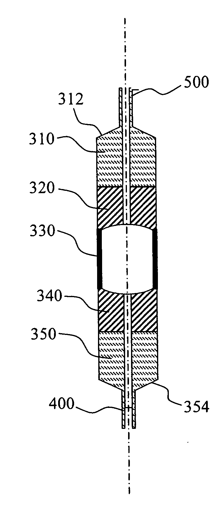
[0033]FIG. 3 shows a preferred embodiment of constituent parts of the sample tube. Desirably, a signal detecting tube 330 that accommodates a sample at the position of the antenna 200 has a length lying between 80% and 100% of the length of the antenna 200, and the signal detecting tube 330 has an inlet end 334 and an outlet end 332. The signal detecting tube 330 is disposed in a region between upper and ...

second embodiment

[0050]Description will be given with reference to the drawing with regard to a preferred embodiment of the configuration of the sample tube described with reference to the first embodiment, in which the injection port of the injection supporting tube 350 and the ejection port of the ejection supporting tube 310 have the form of an internal thread (or a female thread).

[0051]FIG. 7 shows an example of the configuration of the sample tube in which the injection port of the injection supporting tube 350 and the ejection port of the ejection supporting tube 310 have the form of the internal thread (or the female thread). A groove 3200 is cut in the inlet end 354 of the injection supporting tube 350. The groove 3200 is cut with the pitch of threads 3210 of the fitting 2200. Likewise, the thread groove 3200 is cut in the outlet end 312 of the ejection supporting tube 310. The thread groove 3200 is cut with the pitch of the threads 3210 of the fitting 2200.

[0052]The tube 1000 is inserted in...

third embodiment

[0053]In order to achieve the appropriate relative positions of the antenna 200 and the signal detecting tube 330 shown in FIGS. 1 and 2,.what is required is a structure in which one of the injection part and the ejection part can pass through the inside of the antenna 200. Description will now be given with reference to the drawing with regard to a preferred embodiment in which any one of the injection supporting tube 350 and the ejection supporting tube 310 has plural ports.

[0054]FIG. 8 shows the configuration of the sample tube having the injection supporting tube 350 having plural ports. Besides the tube 1000 for sample injection, a capillary 4000 for the injection of a chemical liquid or the like is connected to the injection supporting tube 350. The capillary is made of a glass material or the like, and desirably, the capillary is externally coated with polyimide or the like. A hole is formed in the side of the injection supporting tube 350, and the capillary 4000 is inserted ...


PUM


Abstract

A sample tube is used to ensure uniformity in a static magnetic field and uniformity in electromagnetic wave irradiation for NMR measurement for continuous sample injection. The sample tube is formed of a signal detecting tube having a length lying between 80% and 100% of the length of an antenna, the signal detecting tube accommodating a sample at the position of the antenna; first and second joint tubes each having an outside diameter equal to the outside diameter of the signal detecting tube and having an inside diameter smaller than the inside diameter of the signal detecting tube; and injection and ejection supporting tubes each having an inside diameter smaller than the inside diameter of the signal detecting tube. The first and second joint tubes have magnetic susceptibility matched to or brought close to that of a sample solvent.

Description

CLAIM OF PRIORITY[0001]The present application claims priority from Japanese application JP 2007-134295 filed on May 21, 2007, the content of which is hereby incorporated by reference into this application.BACKGROUND OF THE INVENTION[0002]1. Field of the Invention[0003]The present invention relates to an NMR (nuclear magnetic resonance) measurement apparatus and more particularly to an NMR measurement apparatus having a sample tube capable of sample injection and ejection, while maintaining excellent uniformity in a magnetic field and uniformity in an applied electromagnetic wave.[0004]2. Description of the Related Art[0005]In NMR measurement, a sample, placed in a uniform static magnetic field produced by a magnet, is irradiated by an antenna with an electromagnetic wave corresponding to the Larmor frequency of nuclear spin contained in the sample, and a free-induction decay (hereinafter referred to as “FID”) generated by the nuclear spin is detected by the antenna.[0006]Generally,...

Claims


Application Information

Patent Timeline
Patent Type & Authority Applications(United States)
IPC IPC(8): G01R33/30
CPCG01R33/307
Inventor KITAGAWA, ISAOOKADA, MICHIYASAITOH, KAZUO
Owner HITACHI LTD
Why Eureka
Try Eureka