Non-woven textile microwave patch antennas and components

a technology of microwave patch and antenna, which is applied in the field of microstrip patch or slot antenna, can solve the problems of not being flexible and achieve the effects of increasing separation, not being flexible, and adding weight to the antenna

Inactive Publication Date: 2008-11-27
APPLIED RADAR
View PDF4 Cites 5 Cited by
  • Summary
  • Abstract
  • Description
  • Claims
  • Application Information

AI Technical Summary

Benefits of technology

[0005]Non-woven fabrics are broadly defined as sheet or web structures bonded together by entangling fiber or filaments (and by perforating films) mechanically, thermally or chemically. They are fiat, porous sheets that are made directly from separate fibers or from molten plastic or plastic film. They are not made by weaving or knitting and do not require converting the fibers to yarn. Non-woven fabrics are engineered fabrics that may have a limited life, may be single-use fabric or may be a very durable fabric. By using non-woven fabrics as backing for the conductive parts of these antennas and as spacer materials, patch and stripline antennas can also incorporate an increased separation between the patch array and the ground plane, while remaining lightweight and inexpensive.
[0006]The subject of this invention results from the realization that while microwave patch and stripline antennas are limited by the weight and cost of the spacer material, face fabrics and other materials, the use of non-woven fabrics allows for larger antennas at significantly lighter weight and less cost.
[0007]The antenna of the present invention comprises a ground layer or groundplane, a feed element, an antenna layer, and a corrugated or “dimpled” non-woven fabric dielectric substrate interposed between at least two of the layers. An electromagnetic field is produced between the ground layer and the antenna layer when the feed and ground layers are exposed to electromagnetic energy at frequencies from 400 megahertz to 100 gigahertz for transmission and when the antenna and ground layers are exposed to electromagnetic energy at microwave frequencies of 100 megahertz (100 gigahertz for reception. The ground layer and antenna layers are made of a layer of non-woven textile fabric with an electrically conductive adhesive material such as Shield X to provide light weight and flexibility to the antenna. The spacer layer between the ground layer and the antenna layer is made of a corrugated or dimpled non-woven fabric that provides consistent insulated separation between the ground layer and the antenna layers while having the properties of being light weight, flexible, inexpensive and able to vary the spacing between the antenna plane and the ground plane.

Problems solved by technology

The Teflon spacers add weight to the antennas and are not flexible.

Method used


Image

  • Non-woven textile microwave patch antennas and components
  • Non-woven textile microwave patch antennas and components
  • Non-woven textile microwave patch antennas and components

Examples


Embodiment Construction

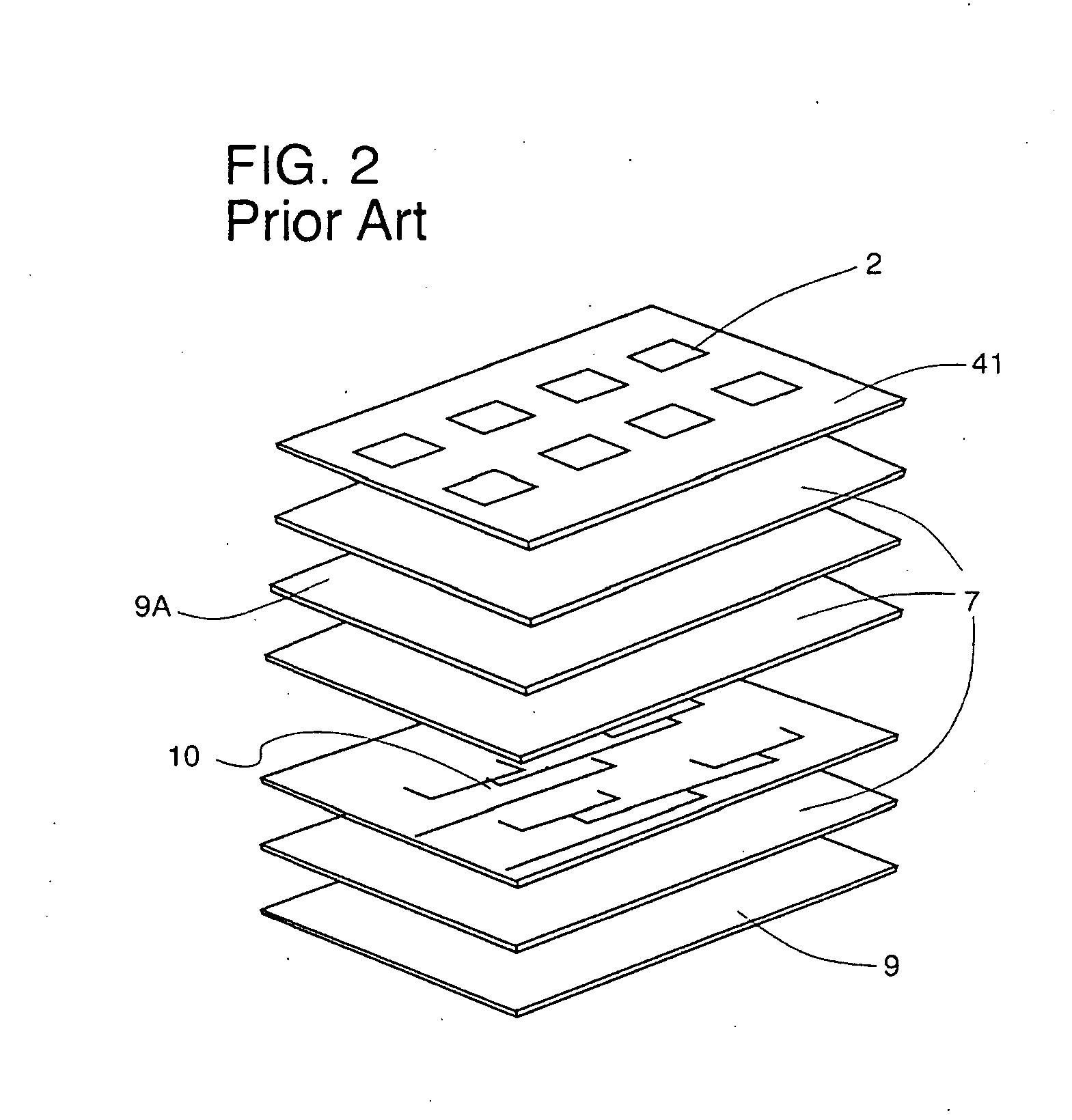
[0023]FIG. 2 is a diagram of the current technology for a multiple patch antenna design which consists of a radiating layer 41 of antenna patches 2, dielectric spacer layer 7 a feed layer 10 that supplies current through the dielectric spacer and an aperturated ground plane 9A. A conventional ground plane 9 at the opposite end of the layers acts to contain the microwave energy. Not shown in layer 9A of this diagram are feed slots or apertures to connect the various radiating layers of the multiple patch antenna.

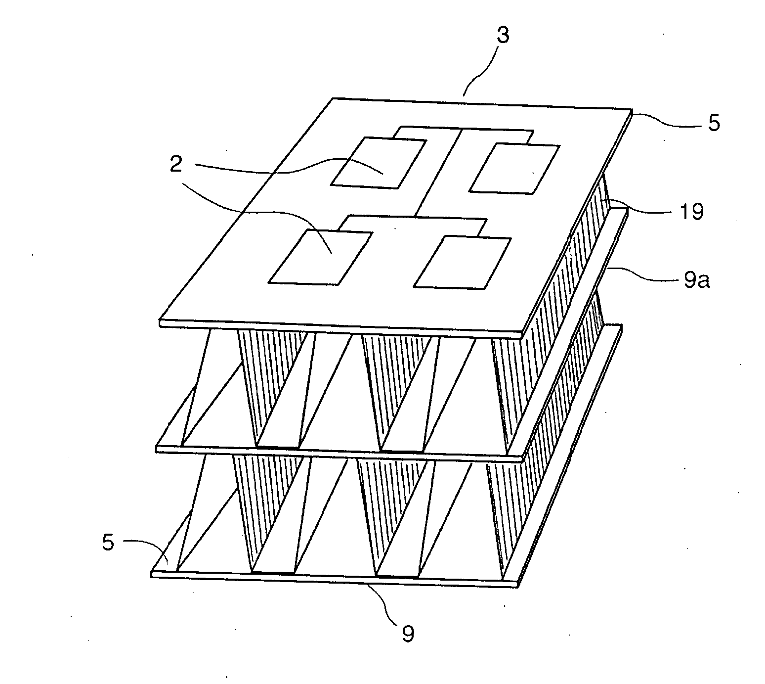
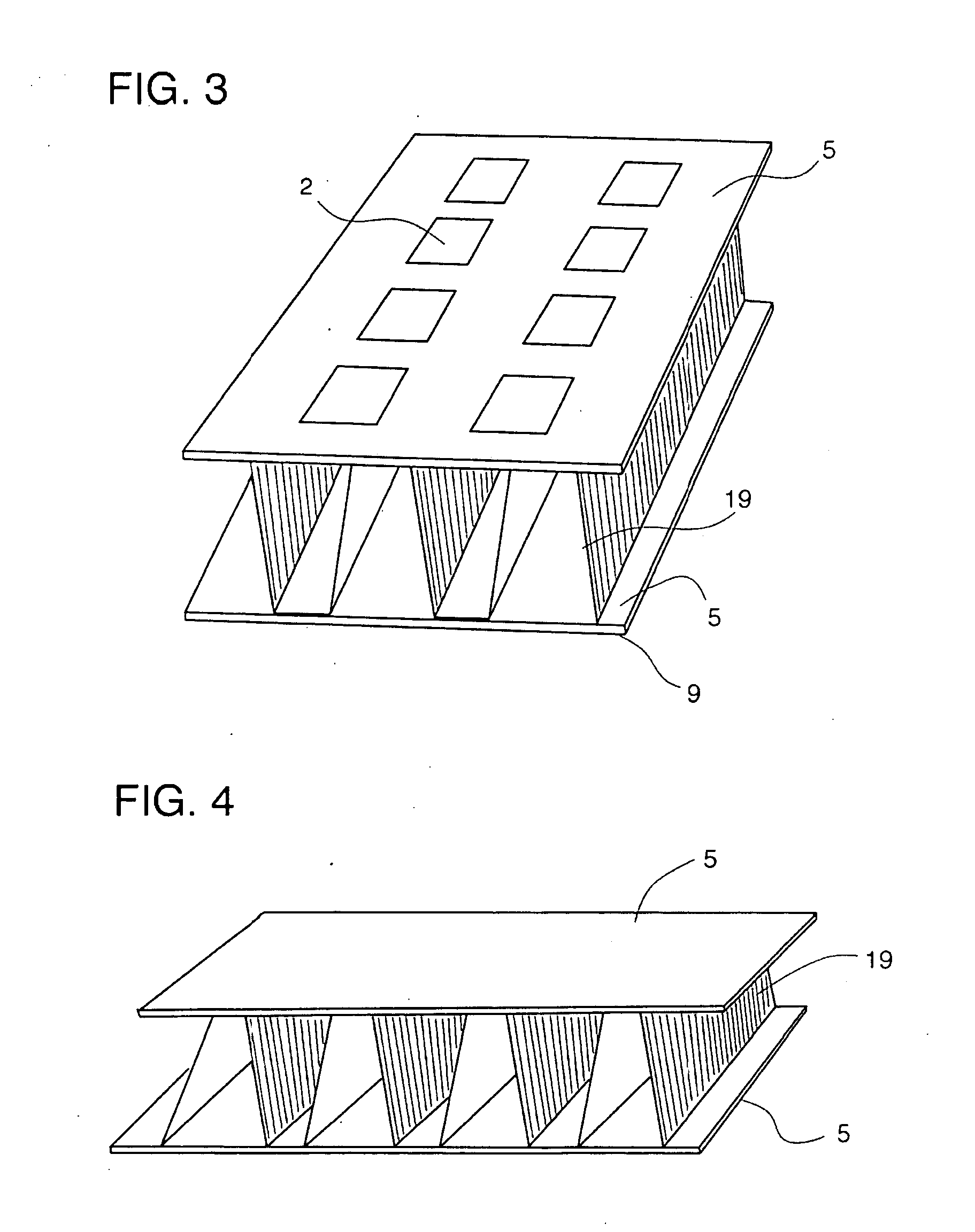
[0024]This detailed description will concern the construction of a three layer micro-strip antenna. FIG. 3 shows a means of constructing a three layer micro-strip antenna where a molded or folded non-woven fabric is incorporated as an interdigitated (corrugated), molded, non-woven spacer fabric 19. Here, the antenna patches 2 and feedlines 3, are cut from a conductive fabric, ShieldX 151, 11, and attached to a retainer non-woven fabric 5. The non-woven dielectric spacer 7 in ...


PUM

PropertyMeasurementUnit
microwave frequenciesaaaaaaaaaa

Abstract

A microwave patch antenna comprising: a plurality of conductive antenna patterns; a plurality of groundplanes; a plurality of feed elements; a plurality of feed slots to allow feed elements to pass through the non-woven dielectric spacers; and a plurality of dielectric separator layers comprised of corrugated non-woven fabric as necessary to form a patch antenna construction.

Description

TECHNICAL FIELD[0001]The present invention relates to an antenna for receiving or transmitting electromagnetic energy at or above microwave frequencies from or to a free space. The present invention more particularly relates to micro-strip patch or slot antennas.BACKGROUND OF THE INVENTION[0002]A micro-strip antenna typically comprises a dielectric substrate having a ground layer, a patch layer spaced apart from the ground layer, and a feed layer electromagnetically communicating with the patch layer. The ground layer, patch layer, and the feed layer are usually made of an electrically conductive material such as copper or other material. In this invention, an electrically conductive adhesive material such as Shield X™ is used along with corrugated or “dimpled” non-woven fabrics to produce an antenna that is both light weight and flexible.[0003]The noun “stripline” as used here is a contraction of the phrase “strip type transmission line, a transmission line formed by a conductor ab...

Claims


Application Information

Patent Timeline
Patent Type & Authority Applications(United States)
IPC IPC(8): H01Q1/38H01P11/00H01Q9/04
CPCH01P11/00Y10T29/49016Y10T29/49018H01Q9/0407
Inventor DEAETT, MICHAEL A.WEEDON, III, WILLIAM H.POURDEYHIMI, BEHNAM
Owner APPLIED RADAR
Why Eureka
Try Eureka