Multiple-input-multiple-output wireless transmission system and transmission method thereof

a wireless transmission system and multi-input technology, applied in the direction of orthogonal multiplex, multiplex communication, transmission path division, etc., can solve the problems of increasing the complexity of the circuit in the receiver system, increasing the number of errors received, and increasing the demand for network capacity and higher performan

Inactive Publication Date: 2008-11-27
NAT CHUNG SHAN INST SCI & TECH
View PDF7 Cites 14 Cited by
  • Summary
  • Abstract
  • Description
  • Claims
  • Application Information

AI Technical Summary

Benefits of technology

[0006]An objective of the present invention is to provide a multiple-input-multiple-output (MIMO) wireless transmission system and a transmission method thereof, which combine the antenna and the frequency-hopping characteristics of MIMO to make each antenna transmit data in different bands. Thereby, the present invention can feature spatial frequency-hopping multiplexing, and the purpose of high-speed transmission can be achieved.

Problems solved by technology

The requests for higher network capacity and higher performance keep growing unceasingly.
However, because a general MIMO wireless transmission system uses multiple sets of transmission antennas in the same band, the transmission is subject to interference from each other, which makes error data receiving.
In order to avoid error data receiving or receiving data transmitted from wrong antennas, the complexity of circuits in the receiver system is increased.

Method used


Image

  • Multiple-input-multiple-output wireless transmission system and transmission method thereof
  • Multiple-input-multiple-output wireless transmission system and transmission method thereof
  • Multiple-input-multiple-output wireless transmission system and transmission method thereof

Examples


Embodiment Construction

[0025]In order to make the structure and characteristics as well as the effectiveness of the present invention to be further understood and recognized, the detailed description of the present invention is provided as follows along with preferred embodiments and accompanying figures.

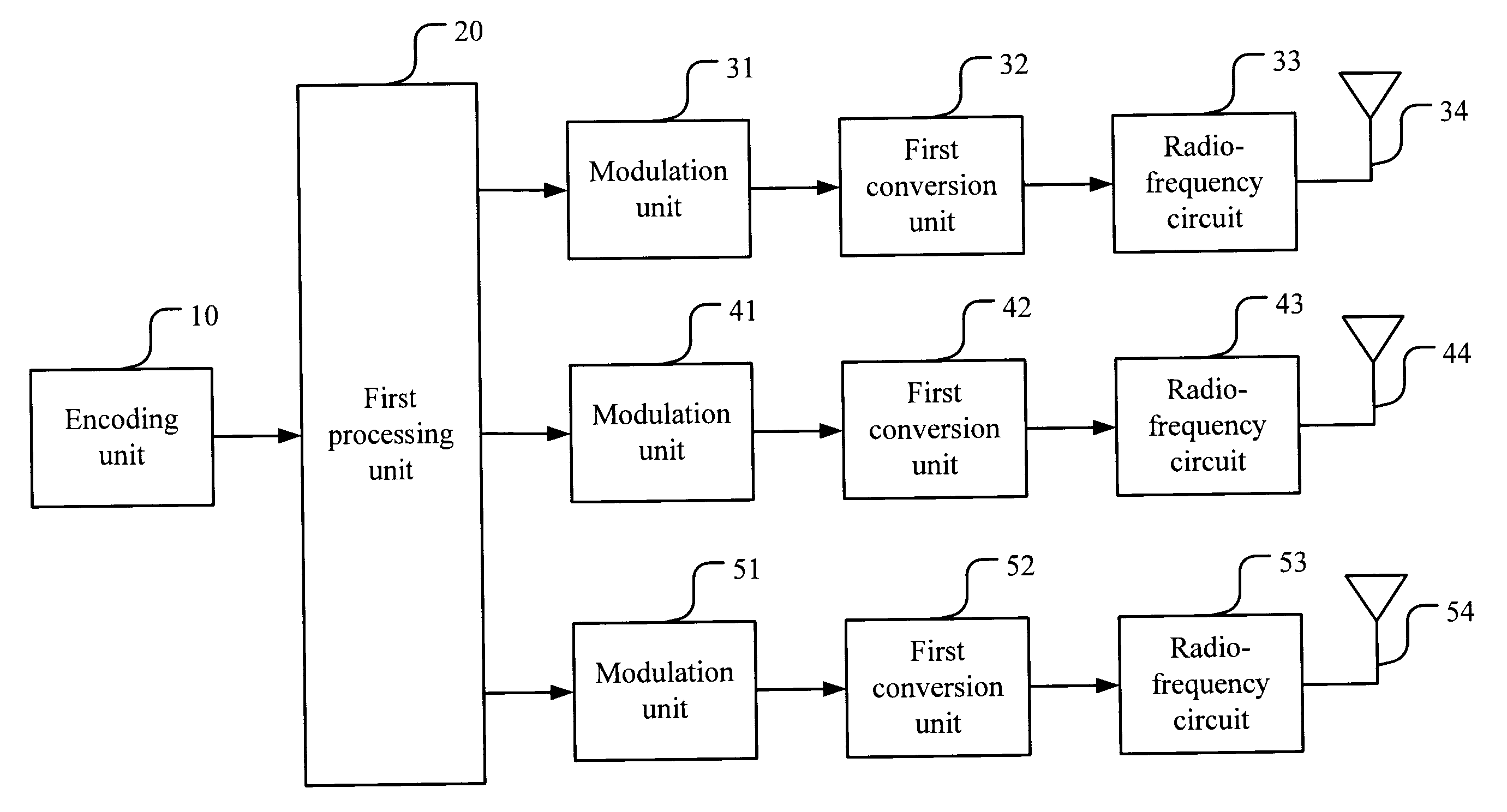
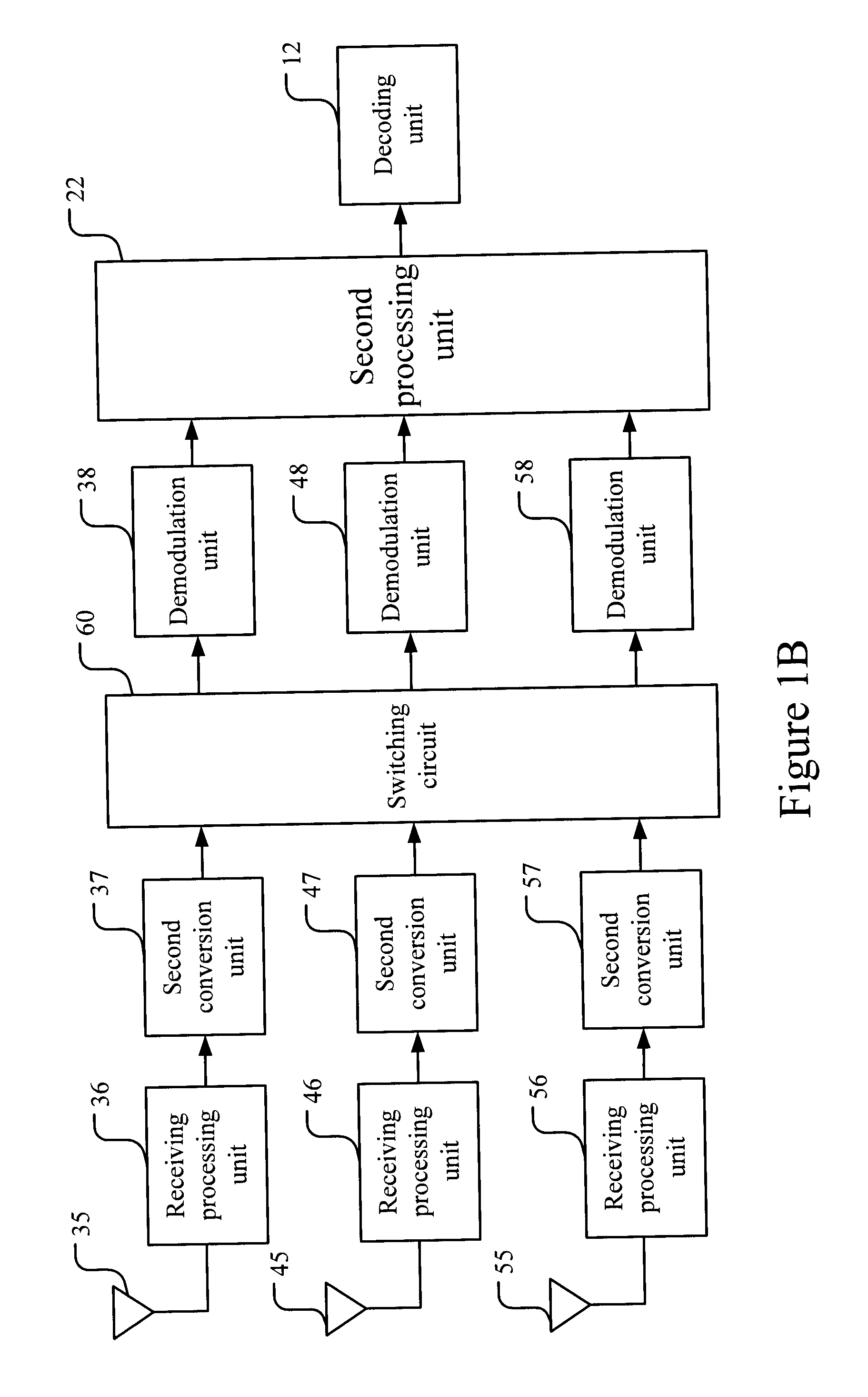
[0026]FIGS. 1A and 1B show the block diagrams according to a preferred embodiment of the present invention. As shown in the figures, the MIMO wireless transmission system includes a wireless transmitting system and a wireless receiving system. FIG. 1A shows the wireless transmitting system, while FIG. 1B shows the wireless receiving system. The wireless transmitting system includes an encoding unit 10, a first processing unit 20, a plurality of modulation units 31, 41, 51, a plurality of first conversion units 32, 42, 52, and a plurality of radio-frequency (RF) circuits 33, 43, 53. The encoding unit 10 receives input data, and encodes the input data to produce encoded data. The encoding unit 10 includes a...


PUM


Abstract

The present invention relates to a multiple-input-multiple-output (MIMO) wireless transmission system and a transmission method thereof. A wireless transmitting system thereof receives encoded data via a first processing unit, which processes the encoded data and outputs the encoded data to a plurality of modulation units for modulating the encoded data to produce a plurality of modulated data. A plurality of first conversion units converts the plurality of modulated data to a plurality of transmitting signals. A plurality of radio-frequency (RF) circuits receives the plurality of transmitting signals and transmits RF signals according to the frequency-hopping sequence of a piconet. A plurality of receiving processing units of a wireless receiving system according to the present invention receives the RF signals, respectively, according to the frequency-hopping sequence of the piconet and transmits to a plurality of second conversion units for converting the RF signals to received data. A switching circuit switches the received data according to the frequency-hopping sequence of the piconet. A plurality of demodulation units demodulates the switched received data to produce demodulated data. A second processing unit received the demodulated data, and processes the demodulated data to output demodulated data. A decoding unit decodes the demodulated data output by the second processing unit to produce output data.

Description

FIELD OF THE INVENTION[0001]The present invention relates generally to a wireless transmission system and a transmission method thereof, and particularly to a multiple-input-multiple-output (MIMO) wireless transmission system and a transmission method thereof.BACKGROUND OF THE INVENTION[0002]In modern society with advanced technologies, electronic products continuously weed through the old to bring forth the new. The importance of wireless communication services rises day by day. The requests for higher network capacity and higher performance keep growing unceasingly. In addition, the demands for wide bandwidth of wireless communication and high data rate have become future goals.[0003]Presently, the ultra wideband (UWB) system appeals people's attention, and has been regarded as a solution for short-distance wireless communications. The advantages thereof include high data rate, low power, and low cost. Besides, international organizations have proposed two technologies currently t...

Claims


Application Information

Patent Timeline
Patent Type & Authority Applications(United States)
IPC IPC(8): H04K1/10H04B1/713H04B7/04H04J11/00H04J99/00H04W12/02
CPCH04B7/0413H04L5/0007H04W12/02
Inventor DENG, JUINN-HURNGHWANG, JENG-KUANGCHUANG, YU-MIN
Owner NAT CHUNG SHAN INST SCI & TECH
Why Eureka
Try Eureka