Method and apparatus for determining optical path attenuation between passive optical network nodes

a technology of optical path attenuation and optical path, which is applied in the direction of electrical equipment, transmission monitoring, transmission monitoring/testing/fault-measurement systems, etc., can solve the problems of increased maintenance and operation costs, limited number of oscs used,

Inactive Publication Date: 2008-11-27
TELLABS PETALUMA
View PDF16 Cites 38 Cited by
  • Summary
  • Abstract
  • Description
  • Claims
  • Application Information

AI Technical Summary

Problems solved by technology

However, a limited number of OSCs may be used because optical signal power drops each time the signal is split.
The complexity of a multipoint PON architecture, together with system operators avoiding interrupting customer service, has increased difficulty of diagnosing and troubleshooting network problems, resulting in increased maintenance and operation costs.

Method used


Image

  • Method and apparatus for determining optical path attenuation between passive optical network nodes
  • Method and apparatus for determining optical path attenuation between passive optical network nodes
  • Method and apparatus for determining optical path attenuation between passive optical network nodes

Examples


Embodiment Construction

[0016]A description of example embodiments of the invention follows.

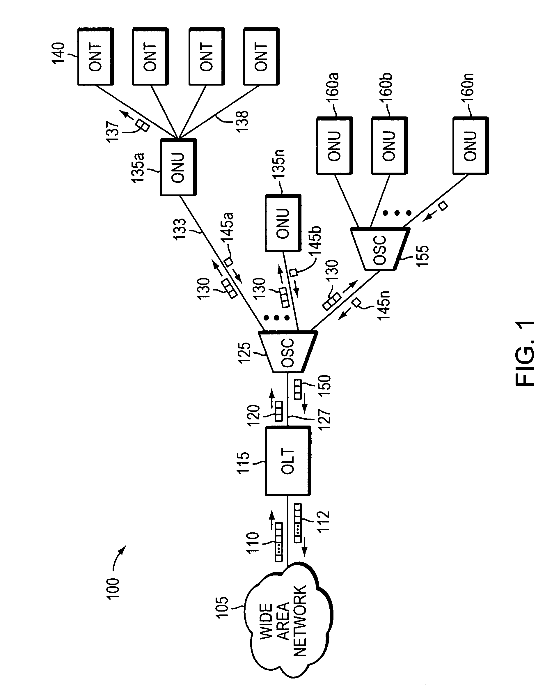
[0017]Early implementation of optical networks were deployed as point-to-point networks. With single end nodes, it was relatively easy to determine operating characteristics of the optical link such as optical signal attenuation. Troubleshooting point-to-point optical networks is also a relatively straightforward process as there are only two network nodes. As service demands have increased, network providers have begun deploying point-to-multipoint passive optical network (PON) architectures.

[0018]The PON architecture allows a service provider to serve multiple users with less equipment and fiber as compared with equivalent point-to-point architectures. Examples include asynchronous transfer mode (ATM) PONs (APON), broadband PONs (BPON), and more recently Ethernet PONs (EPON) as described in Institute of Electrical and Electronics Engineers 802.3ah and gigabit PONs (GPON) as described in International Telecommunica...


PUM


Abstract

A method and apparatus of determining attenuation of an optical path between two optical networks may include using a communications traffic signal without interrupting service or requiring additional external test equipment. A transmit optical network node is configured to measure the transmit power of a transmitted optical signal. A receive optical network node is configured to measure the transmit power of the same transmitted optical signal. A calculation unit calculates the power differential of a transmit and receive optical power. A determination unit is configured to determine optical path attenuation as a function of the optical path distance between the transmit and receive optical network nodes. A reporting unit reports data indicative of the optical path attenuation. The optical path attenuation may be monitored periodically, on demand, on an event basis and may report an alert if the attenuation measurement exceeds a preconfigured threshold. The data may be used to proactively monitor quality of an in-service passive optical network by determining the optical path attenuation.

Description

BACKGROUND OF THE INVENTION[0001]A passive optical network (PON) uses optical fiber to communicate data, video, or audio (herein collectively “data”) between network nodes. As demand for communication services has increased, system operators have increasingly deployed point-to-multipoint PONs. Components such as optical splitter / combiners (OSC) passively split an optical signal into identical copies, allowing a single fiber connection to be shared among multiple users. However, a limited number of OSCs may be used because optical signal power drops each time the signal is split. Thus, a typical PON may use one OSC or perhaps cascade two OSCs. Point-to-multipoint PONs allow a service provider to serve more customers with less equipment thereby decreasing equipment cost on a per user basis.[0002]In a PON, data embedded in a light signal generated by, for example, a laser diode, flows downstream from a transmitting network node, such as an optical line terminal (OLT) to a receiving opt...

Claims


Application Information

Patent Timeline
Patent Type & Authority Applications(United States)
IPC IPC(8): H04B10/08
CPCH04B10/0795
Inventor ORON, MOSHEZUHDI, MUNEER
Owner TELLABS PETALUMA
Why Eureka
Try Eureka