Vehicle transport ramp system

a technology for transportation ramps and vehicles, applied in the direction of loading/unloading vehicles, transportation items, refuse collection, etc., can solve the problems of loss of traction, interruption impair the safety of the vehicle loading process, so as to achieve efficient and quick raising and lowering, and quick and efficient adjustment of the transport vehicle

Active Publication Date: 2008-11-27
DUNKEL PETER L
View PDF28 Cites 23 Cited by
  • Summary
  • Abstract
  • Description
  • Claims
  • Application Information

AI Technical Summary

Benefits of technology

[0009]The vehicle transport ramp system is innovative in that the configuration of the lower ramp being pivotally connected to the upper ramp, as well as the upper ramp and the lower ramp being pivotally mountable to the transport vehicle and the trailer bed, respectively, enable the combined length of the upper ramp and the lower ramp to be significantly increased. This feature may reduce vehicle “hang up” between a transported vehicle and the vehicle loading ramp, which occurs when the undercarriage of the transported vehicle comes into contact with and potentially even “scrapes” the loading ramp. Vehicle “hang up” may result in a loss of traction and the interruption of the vehicle loading process. A vehicle “hang up” may be caused by the pitch of a vehicle loading ramp being so steep as to cause a transported vehicle to abut the surface of the loading ramp with its undercarriage. This may impair the safety of the vehicle loading process, delay its completion, and also cause property damage to the transported vehicle. The increased combined length of the upper ramp and the lower ramp in this vehicle transport ramp system also enables its use on transport vehicles with a higher ground clearance from the distance between the trailer bed and the driving surface. In addition, the increased range of motion of the upper ramp and the lower ramp, in being pivotally mountable to the transport vehicle and the trailer bed, respectively, may enable the use of the vehicle transport ramp system on transport vehicles with a higher ground clearance. Transport vehicles with an increased ground clearance may include those having a 4×4 wheel suspension and drive system. Therefore, the vehicle transport ramp system may uniquely enable transport vehicles equipped to be driven on “off-road” driving surfaces, as well as paved “highway” driving surfaces to safely and efficiently load and unload transported vehicles. Accordingly, the vehicle transport system may reduce the time spent loading and unloading a vehicle into the transport vehicle, improve the traction of the vehicle loading and unloading process, and reduce the potential damage to the undercarriage of the transported vehicle. The vehicle transport ramp system may also expand the potential driving surfaces on which vehicle transport and the vehicle loading and unloading process may be completed. The innovative benefits of the vehicle transport ramp system may find application in a wide variety of transport vehicles, including but not limited to tow trucks, high-profile trailers, recreational vehicles, and any other ground-based vehicles used to transport a transported vehicle.
[0028]Both the lower ramp hydraulic actuator and the lift arm may reduce the effort involved in raising and lowering the lower ramp during the operation of the vehicle transport ramp system.

Problems solved by technology

Vehicle “hang up” may result in a loss of traction and the interruption of the vehicle loading process.
A vehicle “hang up” may be caused by the pitch of a vehicle loading ramp being so steep as to cause a transported vehicle to abut the surface of the loading ramp with its undercarriage.
This may impair the safety of the vehicle loading process, delay its completion, and also cause property damage to the transported vehicle.
Nor do any of the prior art vehicle loading ramp systems appear to use a lower ramp enclosure paneling and a side wall enclosure paneling to enclose the open space created in the transport vehicle as the lower ramp is lowered from an elevated “off-road” driving mode to a “highway” driving mode.
While pivotally connected, the prior art vehicle transport ramp systems appear to be limited for use with wheel suspensions and drive systems intended for single mode usage on paved highways and roads, where there the transport vehicle does not have an increased ground clearance.

Method used


Image

  • Vehicle transport ramp system
  • Vehicle transport ramp system
  • Vehicle transport ramp system

Examples


Embodiment Construction

[0037]The drawings referred to herein are for the purposes of illustrating the preferred embodiments of the present invention and not for the purposes of limiting the same.

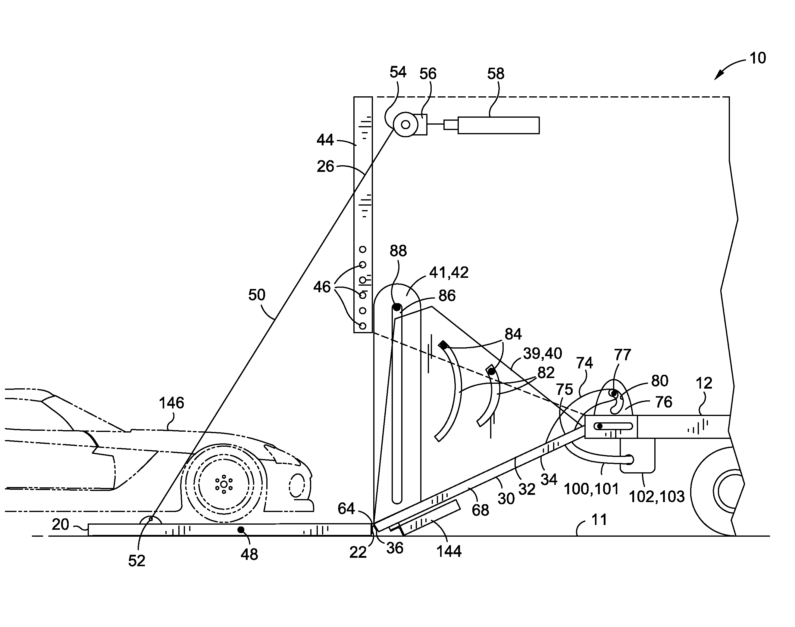
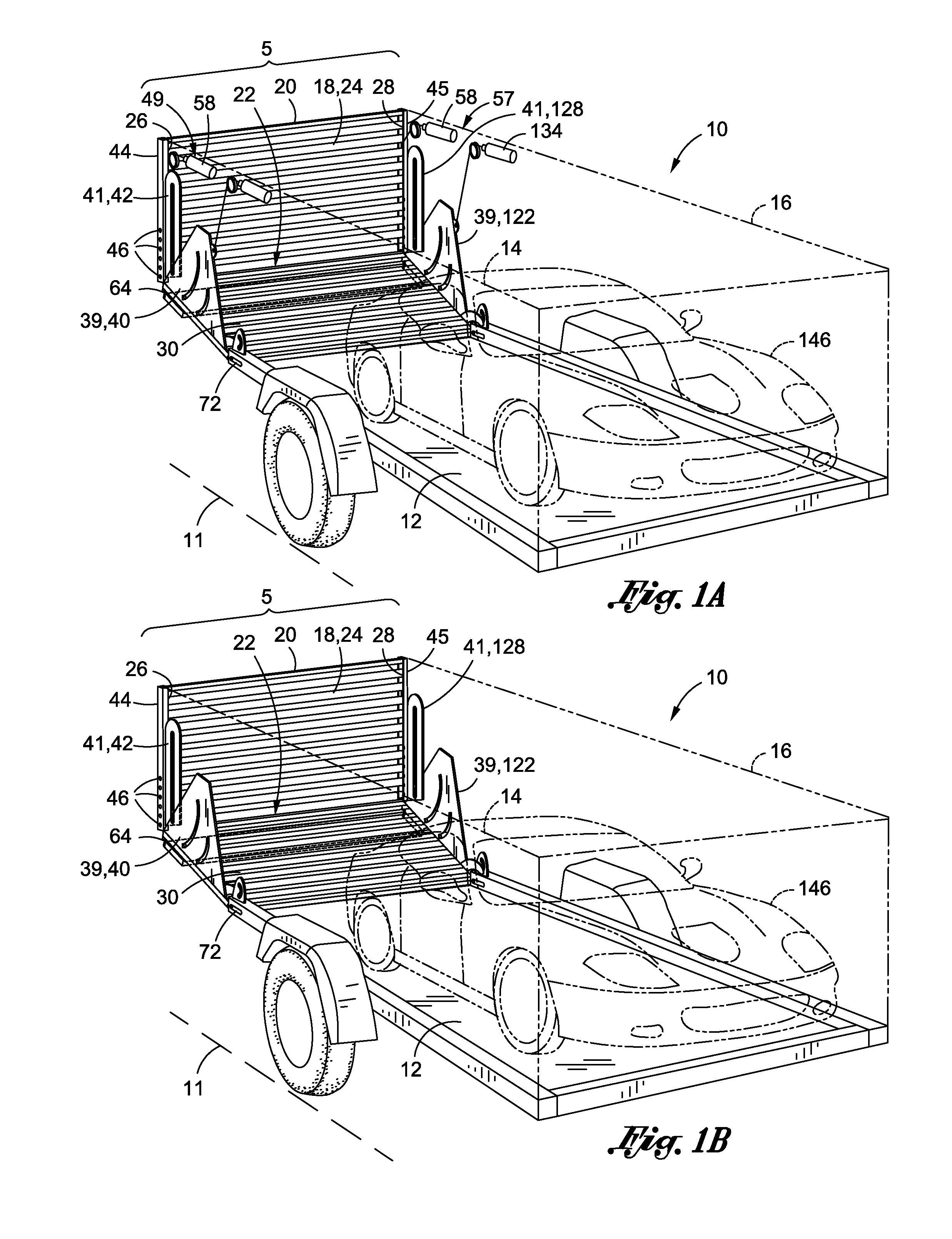
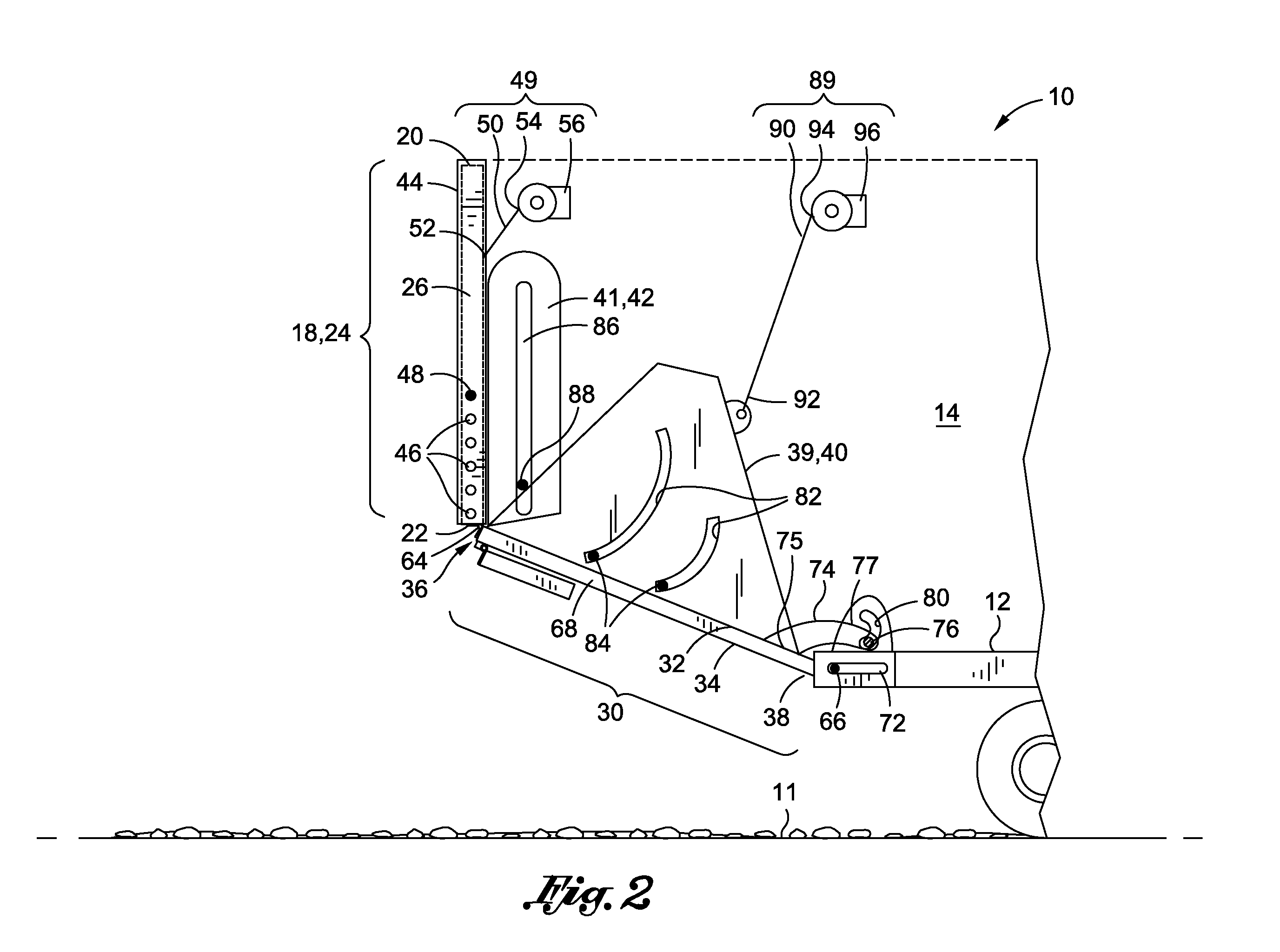
[0038]FIG. 1A is an embodiment of a vehicle transport ramp system 5 used with a transport vehicle 10 having a trailer bed 12, a first side wall 14, and an opposing second side wall 16 about a periphery of the trailer bed 12. A transported vehicle 146 may be positioned on the trailer bed 12 between the first side wall 14 and the second side wall 16. The upper ramp 18 may have a first upper ramp end 20 and a second upper ramp end 22. The upper ramp 18 may further have a first upper ramp edge 26 and an opposing second upper ramp edge 28. The upper ramp 18 may be sized and configured to be mountable to the transport vehicle 10. The upper ramp 18 may be operative to form a door enclosing the rear of the transport vehicle 10. The upper ramp 18 may be defined by an upper ramp plane 24. In this embodiment, the first upper...


PUM


Abstract

A vehicle transport ramp system having a transport vehicle with a trailer bed, a first side wall and an opposing second side wall; an upper ramp having a first upper ramp end and a second upper ramp end operative to form a door, and a first upper ramp edge and an opposing second upper ramp edge; a lower ramp having a first lower ramp side and a second lower ramp side, a first lower ramp edge and a second lower ramp edge, a first lower ramp end pivotally connected to the second upper ramp end, and a second lower ramp end pivotally mountable to the trailer bed; a lower ramp enclosure paneling mountable to the first lower ramp side, and a side wall enclosure paneling to enclose the transport vehicle as the lower ramp is lowered toward the driving surface.

Description

CROSS-REFERENCE TO RELATED APPLICATIONS[0001]This application claims the benefits of U.S. Provisional Patent Application Ser. No. 60 / 939,186 entitled “Vehicle Loading Ramp” filed May 21, 2007, the entire contents of which are expressly incorporated herein by reference.STATEMENT RE: FEDERALLY SPONSORED RESEARCH / DEVELOPMENT[0002]Not ApplicableBACKGROUND[0003]The present invention relates generally to a vehicle transport ramp system for use on most transport vehicles for loading and unloading transported vehicles.[0004]The transport by a larger ground-based transport vehicle of another transported vehicle has traditionally been necessitated by a vehicle's mechanical failure or disablement following an accident. The transport vehicle may also be used to move a specialty vehicle for display at a car show, a motor sport vehicle, or a companion vehicle for use at a vacation destination, such as a remote camp site or cross-country tour. The transported vehicle is commonly pulled by the tran...

Claims


Application Information

Patent Timeline
Patent Type & Authority Applications(United States)
IPC IPC(8): B60P1/43
CPCB60P1/433B60P1/435B60P3/122
Inventor DUNKEL, PETER L.
Owner DUNKEL PETER L
Why Eureka
Try Eureka