Battery module

a battery module and battery technology, applied in the field of batteries, can solve the problems of light weight of spacers, achieve the effects of preventing battery temperature from rising further, preventing temperature elevation or effective fire spreading of batteries

Inactive Publication Date: 2008-11-27
SANYO ELECTRIC CO LTD
View PDF8 Cites 57 Cited by
  • Summary
  • Abstract
  • Description
  • Claims
  • Application Information

AI Technical Summary

Benefits of technology

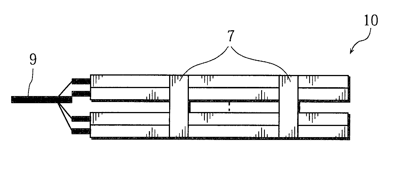
[0015]In the present invention, the at least one spacer interposed between the plurality of batteries in the battery module has an inner cavity, a filling agent having fire-extinguishing capability is filled in the inner cavity, and an opening can be formed at least a portion of the spacer by heat so that the filling agent can flow out of the spacer. Therefore, when the battery temperature rises, the heat is insulated and/or dissipated by the spacer in which the filling agent is filled in the inner cavity, so the battery temperature is prevented from rising further. Moreover, after an opening is formed in at least a portion of the spacer and the filling agent flows out, the inner cavity of the spacer is emptied and an air space is formed. This air space makes the heat insulation more effective, and therefore, even if abnormal heat generation occurs in one of the plurality of batteries, the abnormal heat generation is prevented from spreading to other batteries reliably. Furthermore, even if one of the plurality of batteries ignites, the spacer, in which the filling agent having fire-extinguishing capability is filled, can prevent spreading of the

Problems solved by technology

Furthermore, because the spacer has an inner cavity, the spacer is lightweight even when the spacer is made of metal.
In addition, because the fillin

Method used


Image

  • Battery module
  • Battery module
  • Battery module

Examples


first example

Example A1

[0113]A battery module fabricated in the same manner as described in the foregoing embodiment was used as the battery module of Example A1.

[0114]The battery module thus fabricated is hereinafter referred to as a battery module A1.

example b1

[0115]A battery module was fabricated in the same manner as described in Example A1 above, except for using B-type spacers 52 that were prepared in the following manner, in place of the A-type spacers 51 used in Example 1.

[0116]Plate materials made of polyethylene terephthalate (PET), each having a thickness of 1 mm, were bonded together to form a square-shaped pouch-type container, and water was filled therein as liquid. Lastly, a Bi—Cd—Pb—Sn alloy (with a mass ratio Bi:Cd:Pb:Sn=50:10:25:15 and a melting point of 75° C.) formed into a small piece with dimensions of 5 mm×10 mm×0.5 mm was bonded as a lid to one end of one peripheral edge of the pouch-type container, as illustrated in FIG. 9, to form a low-melting point portion 14. Thus, a spacer 52 (hereinafter referred to as a “B-type spacer”) in which liquid was enclosed was prepared. The spacer 52 had a width of 120 mm, a height of 150 mm, and a thickness of 5 mm.

[0117]The battery module fabricated in this manner is hereinafter re...

second example

Preparation of Pouch-Type Container

[0123]As illustrated in FIG. 11, plate materials made of polyethylene terephthalate (PET) were bonded to form a square-shaped pouch-type container. Through holes each with a diameter of about several millimeters were formed at two locations in one of the plate materials that formed one side of the pouch-type container, one location being at a lower end of the container and the other location being at a central portion thereof that is located above the lower location and spaced at a gap S11=50 mm therefrom. Next, water as liquid was filled in the pouch-type container from the just-mentioned through holes. Thereafter, a Bi—Cd—Pb—Sn alloy (with a mass ratio Bi:Cd:Pb:Sn=50:10:25:15 and a melting point of 75° C.) was formed into small pieces each with dimensions of 10 mm×10 mm×0.5 mm to form lids. The lids were bonded by adhesive so as to cover the upper and lower through holes. Thereby, two low-melting point portions 15L and 15H were formed so as to be...


PUM


Abstract

A spacer (52) interposed between a plurality of batteries in a battery module has an inner cavity. A filling agent having fire-extinguishing capability is filled in the inner cavity. An opening can be formed at a portion (low-melting point portion (14)) of the spacer (52) by heat so that the filling agent can flow out of the spacer.

Description

BACKGROUND OF THE INVENTION[0001]1. Field of the Invention[0002]The present invention relates to a battery module comprising a plurality of batteries, and more particularly to a battery module that is lightweight and safe, and shows high load characteristics and high reliability.[0003]2. Description of Related Art[0004]Power sources that are incorporated in robots and electric automobiles, for example, are required to be lightweight and small in size, as well as being low cost, because they are enclosed in a limited space. Lithium-ion batteries, which have high energy density, have attracted attention as a battery that meets such requirements. In order to obtain high power, the lithium-ion batteries are used to form a battery module, which contains a large number of the lithium-ion batteries, typically from several cells to over 10 cells, connected in series or in parallel.[0005]During charging and discharging of the lithium-ion batteries, the battery temperature may rise. If the ba...

Claims


Application Information

Patent Timeline
IPC IPC(8): H01M2/14H01M10/50H01M6/42H01M50/105H01M50/211
CPCH01M2/0207H01M2/1061H01M2200/10H01M2200/00H01M2/1235Y02E60/10H01M50/342H01M50/105H01M50/211
Inventor MAEDA, HITOSHIFUJIWARA, MASAYUKISHINYASHIKI, YOSHITAKAFUNAHASHI, ATSUHIRO
Owner SANYO ELECTRIC CO LTD
Why Eureka
Try Eureka